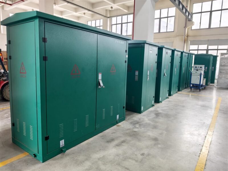
Why Medium Voltage Cable Sizing Matters
Cable sizing is one of the few decisions in a medium voltage project that affects safety, cost and reliability at the same time. A cable that is too small runs hot, ages faster and may fail long before its design life. A cable that is too large wastes money on copper and needs bigger joints and terminations.
In practice, sizing is not a single number taken from a table. It is a chain of checks: continuous current, derating for installation conditions, voltage drop, short circuit withstand and mechanical fit. Skip one step and the design looks correct on paper but fails in service. This guide walks through the eight steps we use when specifying cables for switchgear, ring main units and compact substations.
Inputs You Must Collect First
Before any calculation, gather the real project data. Guessing here is the most common source of rework.
- Design current. Take the maximum continuous load, not the average.
- System voltage. 11kV, 24kV, 33kV or 40.5kV, and the insulation level (Um).
- Fault level. Prospective short circuit current and its duration, usually 1 s or 3 s.
- Installation method. In air, in duct, buried in soil, in a tray or inside a panel.
- Ambient conditions. Air temperature, soil temperature, soil thermal resistivity.
- Route details. Cable grouping, buried depth, adjacent heat sources, future expansion.
- Voltage drop limit. Usually 3 to 5 percent for distribution feeders.
Every one of these values changes the final cross section. A 240 mm² cable in free air may carry more current than a 300 mm² cable buried in dry, hot soil.
The 8-Step Sizing Method
Step 1: Calculate the design current. Use the connected load with the appropriate diversity factor, then convert to amps at the nominal voltage.
Step 2: Choose a preliminary cross section. Start from the manufacturer current table for the intended installation method.
Step 3: Apply derating factors. Correct for ambient temperature, soil resistivity, burial depth and grouping. Multiply all factors together; never add them.
Step 4: Compare with the corrected capacity. The derated capacity must exceed the design current with a margin, typically 10 to 20 percent.
Step 5: Check voltage drop. Use the cable resistance and reactance at the operating temperature, not the 20 degrees Celsius values.
Step 6: Check short circuit withstand. Apply the adiabatic equation and confirm the conductor and screen survive the fault duration.
Step 7: Check physical limits. Confirm the cable fits the gland, the termination kit and the switchgear cable entry.
Step 8: Document the result. Record every input, factor and assumption so the design can be reviewed later.
The same logic applies when you size cables between a switchgear panel and a transformer, or between an RMU and a customer feeder.
Current Carrying Capacity Reference
The table below gives typical values for copper and aluminium XLPE cables at 6/10 kV, installed in air at 30 degrees Celsius. Treat it as a starting point only: always confirm with the cable maker data and the standard you are working to.
| Cross section (mm2) | Cu in air (A) | Al in air (A) | Cu DC resistance (ohm/km) |
|---|---|---|---|
| 25 | 125 | 96 | 0.727 |
| 35 | 150 | 115 | 0.524 |
| 50 | 180 | 140 | 0.387 |
| 70 | 225 | 175 | 0.268 |
| 95 | 270 | 210 | 0.193 |
| 120 | 310 | 240 | 0.153 |
| 150 | 350 | 270 | 0.124 |
| 185 | 400 | 310 | 0.099 |
| 240 | 470 | 365 | 0.075 |
For buried cables the values drop quickly. Dry soil, high thermal resistivity and deep burial can remove 20 to 30 percent of the capacity shown above.
Voltage Drop Check
Voltage drop is often the check that forces a larger cable. Use this simplified formula for a three phase feeder:
Voltage drop (V) = 1.732 x I x L x (R cos phi + X sin phi)
Where I is the design current, L the route length in kilometres, R and X the resistance and reactance per kilometre at operating temperature. A feeder that passes the current check can still fail the voltage drop check, especially at 33kV with long runs to remote load centres.
Keep the result inside the project limit. If the drop is too high, options are a larger cross section, a shorter route, or a different tap setting on the transformer.
Short Circuit Withstand and Screen Selection
Fault current heats the conductor in a fraction of a second. The adiabatic check confirms the conductor survives:
S = I x square root of (t) / k
Where S is the minimum cross section in mm2, I the fault current in amps, t the duration in seconds and k a material constant. For copper XLPE cables k is around 143.
Do not forget the copper screen or sheath. A cable with a generous conductor but a thin screen can fail during a single phase fault. Specify the screen area with the fault level and duration in mind, not just the phase conductor.
Common Sizing Mistakes
- Using the 20 degrees Celsius resistance for voltage drop instead of the operating value.
- Adding derating factors instead of multiplying them.
- Ignoring grouping when several cables share one trench.
- Sizing only for today load and leaving no margin for expansion.
- Forgetting the screen check for short circuit.
- Choosing a cable that does not fit the termination kit or the cable entry.
Our RMU cable termination guide covers the installation side, and the switchgear testing guide explains how to verify the finished connection. For maintenance routines that catch overheated joints early, see the MV switchgear maintenance plan.
Frequently Asked Questions
What is the minimum size for a medium voltage cable?
There is no single minimum. Practical designs usually start at 25 or 35 mm2 for short runs, but the final size comes from the current, voltage drop and short circuit checks.
How much voltage drop is acceptable?
Most distribution projects limit voltage drop to about 3 to 5 percent. Check the project specification, because utility rules can be stricter.
Should I use copper or aluminium?
Copper gives higher conductivity and smaller joints. Aluminium costs less and suits large cross sections. Decide on life cycle cost, weight and joint availability.
Why does burial reduce current capacity?
Soil removes heat more slowly than air, and dry or sandy soil removes it very slowly. The cable runs hotter for the same current, so the permissible current falls.
How long should a cable last?
A correctly sized and installed XLPE cable can serve 25 to 30 years or more. Overheating and moisture ingress are the main causes of early failure.
Do I need a soil thermal test?
For heavily loaded or tightly grouped buried feeders, yes. It removes guesswork from the derating factor and often pays for itself in avoided oversizing.
About Electric-GS
Electric-GS is an OEM and ODM manufacturer in Yueqing, China, producing medium voltage switchgear, ring main units, SF6 GIS, vacuum circuit breakers and compact substations. We help projects match cable entries, glands and terminations to the panel design. Contact us at info@electric-gs.com or WhatsApp +86 135 8897 8050. See the Electric-GS global site and our China site, or read the 33kV switchgear buying guide before you finalize the single line diagram.
One thought