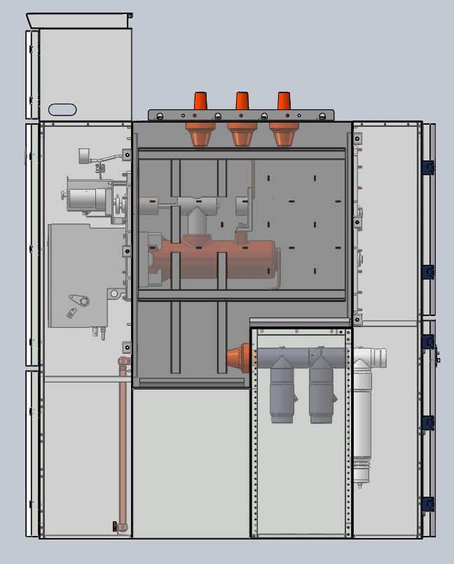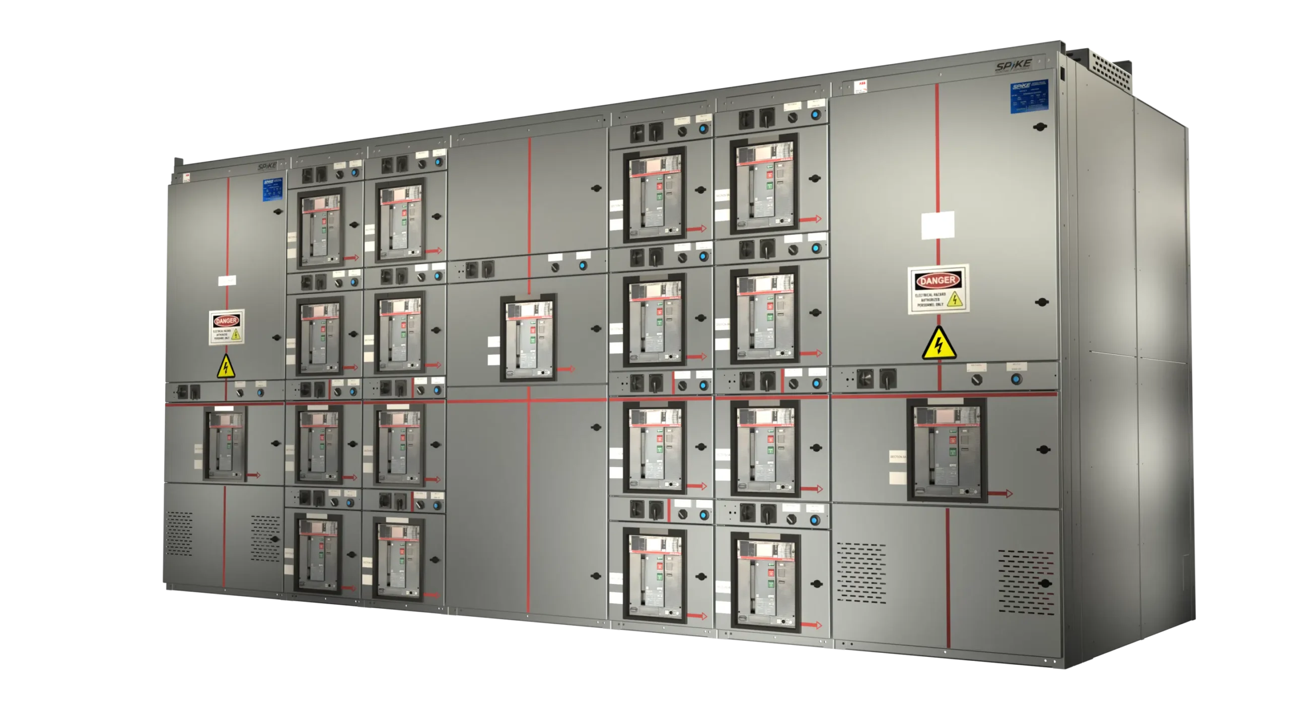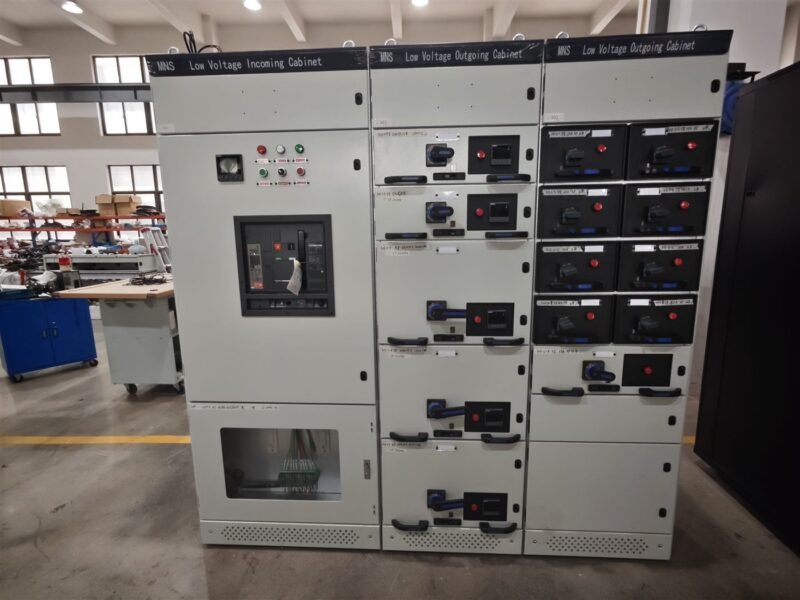
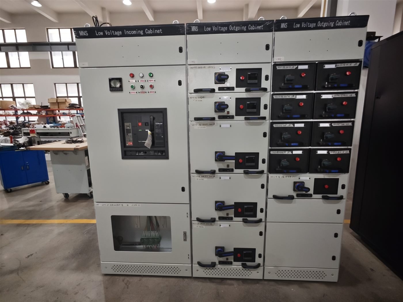
A PT cabinet looks like the simplest cubicle on the drawing. It has no breaker, no trip coil, and usually no operator. That is exactly why it gets approved without review, and why the problems surface later, usually as a metering error nobody can explain or a fuse that ruptures during a switching operation.
The PT cabinet is a protection and metering interface, not a spare compartment. Here are the six points we check before a drawing is released for production.
What a PT Cabinet Actually Does
The cabinet carries voltage transformers that step the busbar voltage down to values the relays and meters can read. It also supplies the control circuits that need a voltage reference. Everything in it exists to give a correct, isolated signal to equipment that is not rated for the busbar voltage.
Two duties are mixed in one cubicle and they do not always want the same transformer. Metering accuracy and protection speed are separate requirements, and a single VT type rarely satisfies both at the highest level. Deciding which duty dominates is the first design choice, and it is covered in more depth in our instrument transformer guide.
| Item | Typical specification | What to confirm before approval |
|---|---|---|
| Voltage transformer | 11 kV or 33 kV, ratio 11/√3 : 110/√3 kV | Accuracy class 0.5 for metering, 3P for protection |
| VT fuse | HV HRC fuse matched to the VT | Fuse rating and breaking capacity, not just size |
| Busbar | Copper, 630 A or 1250 A | Rated for the fault level of the board, not the load |
| Interlock | VT isolated before the door opens | Mechanical, not a label or a procedure |
| Secondary wiring | 2.5 mm² screened cable | Terminal blocks, ferrules and test links present |
For export projects the table is only the starting point. The destination standard decides the accuracy class, the terminal marking and the language of the nameplate, and those three items are usually fixed by the customer’s specification rather than by the switchgear maker. A PT cabinet that meets the drawing but not the local standard will fail at site acceptance, and the fix is rarely limited to the cubicle.
6 Checks Before You Approve the Layout
- Confirm the VT ratio and burden against the real relay set. The ratio follows the busbar voltage, but the burden follows the devices actually connected. A 20 VA transformer with five devices on the circuit is a design error that shows up as a low reading.
- Check the accuracy class duty by duty. Metering classes are defined at a stated burden and power factor. If the meter and the protection relay share one VT, state which duty sets the class.
- Verify the fuse co-ordination. The VT fuse protects the transformer, not the busbar. Its rating must clear a VT fault without operating on normal inrush, and it must not be a substitute for the upstream protection.
- Look at the secondary earthing and test facilities. The secondary neutral must be earthed at one point only, and test links should let a technician isolate a circuit without opening the panel.
- Check the interlock and the access route. The VT compartment must be isolated from the live busbar before the door opens. This belongs with the interlocks in our interlocking system guide.
- Confirm clearances and terminal spacing. Phase spacing, creepage distance and the room for a cable gland are fixed at the layout stage. Reworking them after the enclosure is fabricated is expensive and rarely clean.
Points three and five are where most of our drawing comments land. Fuse selection is covered in the MV fuse selection notes, and the ratio question connects directly to the CT selection criteria used on the same board.
Errors That Appear at Commissioning
- Phase sequence reversed on the secondary. The VT is correct and the wiring is not. Commissioning tests catch it, but only if someone reads the results.
- One VT shared across duties. Protection responds slowly or metering drifts, depending on which class won the argument at the design stage.
- Secondary earthed in two places. Circulating current produces a small, permanent error that is hard to trace after handover.
- No test link on the terminal block. Every later maintenance task then involves opening the compartment instead of isolating a circuit.
- Fuse alarm omitted. A blown VT fuse disables metering and protection without a visible signal, which is the failure mode described in the commissioning test sequence we recommend.
None of these are manufacturing faults. They are decisions taken, or not taken, on the drawing, and they cost nothing to fix before the steel is cut.
FAQ
What is the difference between a PT cabinet and a metering cubicle?
Very little in hardware. The name reflects the duty. A PT cabinet supplies voltage signals; a metering cubicle may also carry CTs, meters and communication equipment.
Can one VT serve both metering and protection?
Yes, when the accuracy class and burden suit both. State that requirement on the drawing, otherwise the supplier will optimise for the cheaper duty.
Which accuracy class should I specify for revenue metering?
Class 0.5 is the usual export requirement. Class 0.2 costs more and is only worth it where the tariff settlement depends on it.
Is a VT fuse mandatory on every PT cabinet?
It is standard practice on MV voltage transformers and protects the transformer from a secondary short. Confirm the fuse type against the VT’s thermal rating.
How often should the PT cabinet be inspected?
At every routine maintenance interval, and after any switching event that produced an alarm. Fuse continuity and secondary earthing are the two items that matter most.
About Electric-GS
Electric-GS is an OEM/ODM switchgear factory in Yueqing, Zhejiang, China. We build PT cabinets, ring main units, MV and LV switchgear and packaged substations to your single line diagram, and we comment on VT ratio, class and interlocking before fabrication starts. Send drawings to info@electric-gs.com or WhatsApp +86 135 8897 8050. English pages are on electricgs.com, Chinese technical notes on electric-cn.com.