Why Current Transformer Selection Matters
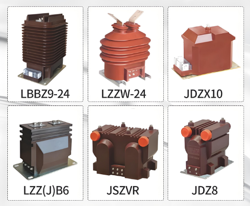
Current transformers (CTs) are the eyes of every medium voltage protection and metering scheme. They step down primary currents to a safe, standardized secondary level, typically 1A or 5A, so that relays, meters, and instruments can operate accurately and safely. Incorrect CT selection leads to metering errors, nuisance trips, or protection failures during faults, which can cause extensive equipment damage. This guide explains the key parameters and a practical selection workflow for MV CTs.
For CT product specifications and custom manufacturing, visit electricgs.com or our factory site at electric-cn.com.
Key CT Parameters Explained
- Rated transformation ratio: The primary to secondary current ratio, such as 200/5A or 600/1A, selected based on the circuit’s normal and maximum load current.
- Accuracy class: Defines the CT’s measurement precision. Class 0.2S/0.5S for billing metering, class 5P10/5P20 for protection applications.
- Burden: The maximum load (in VA) the CT can supply at rated accuracy, including relay, wiring, and meter impedance.
- Instrument security factor (ISF): The ratio of the highest primary current at which the CT maintains accuracy, important for metering protection against overcurrent damage.
- Accuracy limit factor (ALF): For protection CTs, the multiple of rated current at which the CT maintains specified accuracy, critical for through-fault stability.
- Rated short-time thermal current: The short-circuit current the CT can withstand thermally and dynamically.
CT Selection Table
| Application | Accuracy Class | Ratio Selection | Burden |
|---|---|---|---|
| Revenue metering | 0.2S / 0.5S | Full load current ~ 80-120% of CT rating | 5-15 VA |
| Panel indication | 0.5 / 1.0 | Full load ~ 80-100% | 2.5-5 VA |
| Overcurrent protection | 5P10 / 5P20 | Full load ~ 100-150% | 10-30 VA |
| Differential protection | 5P20 / 10P20 | Matched sets for stability | 15-30 VA |
| Earth fault protection | 5P10 | Lower ratio for sensitivity | 5-15 VA |
Step-by-Step CT Selection Process
- Determine application: Identify whether the CT serves metering, protection, or both, since each has different accuracy requirements.
- Calculate load current: Determine the circuit’s normal full-load current and maximum through-fault current.
- Select ratio: For metering, choose a primary rating where normal load is 80-120% of rated value; for protection, where full load is 100-150%.
- Calculate burden: Sum the VA consumption of all connected devices and wiring, and select a CT with adequate rated burden.
- Verify accuracy: Confirm the accuracy class and ALF/ISF match the protection or metering application requirements.
- Check thermal rating: Ensure the CT’s short-time thermal current exceeds the network’s maximum fault current for the clearing time.

Metering vs Protection CTs: What Not to Mix
Metering and protection CTs are designed for different performance regions. Metering CTs maintain accuracy at normal operating currents and saturate during faults to protect connected instruments. Protection CTs must remain accurate at high multiples of rated current, typically 10-20 times, so relays can detect faults reliably. Installing a metering CT in a protection circuit risks relay misoperation; installing a protection CT in a metering circuit can damage meters during faults. Some applications use dual-core CTs combining both functions in one unit with separate cores.
Common CT Selection Mistakes
1. Oversized Ratio
Selecting a CT with a ratio far above the actual load reduces metering accuracy at normal currents and makes low-current faults undetectable.
2. Underestimated Burden
Ignoring wiring resistance and multiple devices in series leads to burden overload, causing the CT to operate outside its accuracy class.
3. Wrong ALF
Choosing a protection CT with insufficient accuracy limit factor causes saturation during through-faults and protection miscoordination.
Frequently Asked Questions
Q1: What is the difference between 5P10 and 5P20 CT?
Both are protection classes: the first digit is the composite error limit (5%), and the number after P is the accuracy limit factor. 5P20 remains accurate up to 20 times rated current, while 5P10 only to 10 times.
Q2: Should I choose 1A or 5A secondary?
Use 1A secondary for long wiring runs and high burden applications to reduce wiring losses, and 5A secondary for standard short-distance installations with conventional relays.
Q3: Can one CT serve both metering and protection?
Yes, dual-core CTs provide separate cores for metering and protection in a single primary assembly, a common solution in MV switchgear panels.
Q4: How do I verify a CT’s accuracy class?
Refer to the nameplate and type test certificate. Factory tests per IEC 61869-2 verify accuracy, and routine tests should be performed after repairs.
Q5: Do you manufacture custom CTs?
Yes, we manufacture MV CTs and combined CT/VT units with custom ratios, classes, and physical dimensions to fit your switchgear design.
About Electric-GS Manufacturer
Electric-GS is a professional electrical power equipment manufacturer based in Liushi, Yueqing, Zhejiang, China, with over 15 years of OEM/ODM experience serving global power equipment distributors and EPC contractors. We supply medium and low voltage switchgear, RMUs, circuit breakers, transformers, and solar balance of system products with full type test reports.
Contact us for quotations and custom design support: Email info@electric-gs.com, WhatsApp: +86 135 8897 8050.