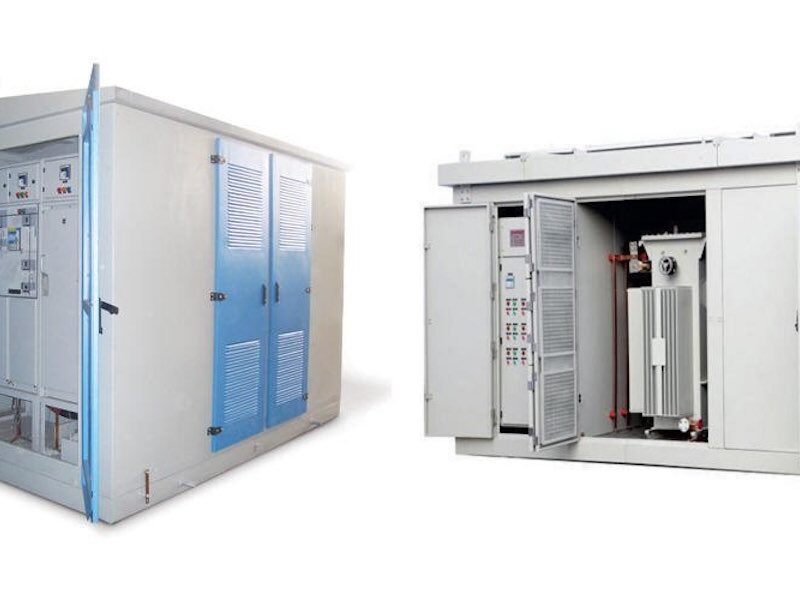
Electric-GS is an experienced manufacturer of medium voltage and low voltage electrical equipment in Yueqing, Zhejiang, China. This engineering guide helps buyers, contractors and engineers make correct and safe decisions for power distribution and renewable energy projects.
Why Earthing Is the Most Important Safety System
When a fault occurs inside a substation, the earthing system carries fault current into the earth and keeps the voltage rise of exposed metal parts within safe limits. A poor earth grid can turn a simple fault into a fatal electric shock. Substation earthing design is therefore a legal and engineering requirement, not an optional extra.
This guide explains the design process step by step and includes a real calculation example you can adapt to your project.
Step 1: Measure Soil Resistivity
Everything starts with soil resistivity, measured in ohm-meters. Use the Wenner four-probe method at several points across the site, at depths related to the planned grid size. Soil resistivity varies with moisture, temperature and depth, so measure in different seasons if possible.

Step 2: Define the Target Earth Resistance
Most standards require a station earth resistance below 1 ohm for large HV substations and below 4 ohms for typical MV substations. The exact target depends on the fault current level and the allowable touch and step voltages. Check the local utility rules and IEC 60364 / IEEE 80 requirements for your project.
Step 3: Choose the Grid Layout
The earth grid is a mesh of bare copper conductors buried about 0.5-0.8m deep, covering the whole substation area. Grid spacing of 3m x 3m to 10m x 10m is common. Smaller spacing lowers step and touch voltages but increases cost.
| Grid Spacing | Resistance Contribution | Cost |
|---|---|---|
| 10m x 10m | Low | Low |
| 5m x 5m | Medium | Medium |
| 3m x 3m | High (lowest voltage) | High |
Step 4: Calculate Earth Resistance
For a rectangular grid, a simplified formula is R = (rho / (4r)) + (rho / L), where rho is soil resistivity in ohm-meters, r is the equivalent radius of the grid in meters, and L is the total buried conductor length in meters.
Calculation Example
Assume soil resistivity rho = 100 ohm-m, and a 20m x 20m grid. Equivalent radius r = sqrt(A / pi) = sqrt(400 / 3.1416) = 11.28m. With a total conductor length L of 400m (spacing about 5m), R = 100 / (4 x 11.28) + 100 / 400 = 2.22 + 0.25 = 2.47 ohms. This is below the 4 ohm target for a MV substation, so the design is acceptable for the earth resistance requirement.
If the calculated value is too high, add more grid conductors, install vertical earth rods, or treat the soil with conductive backfill.

Step 5: Check Touch and Step Voltage
Even with low earth resistance, the touch and step voltages during a fault must stay below the limits for human safety. Use the grid geometry, fault current split and soil model to calculate these values per IEEE 80. Where limits are exceeded, reduce grid spacing, add a surface layer of crushed stone (which raises the surface resistivity), or deepen the grid.
Step 6: Select Materials and Connections
- Grid conductors: bare copper, minimum 70mm2 for MV substations
- Earth rods: copper-bonded steel, 2-3m long, driven at grid intersections
- Connections: exothermic welding or compression lugs, never simple bolting
- Test points: accessible links at the fence, equipment and neutral
- Surface layer: 10-15cm of crushed rock around operating areas
Step 7: Connect All Equipment and Test
Every metallic structure in the substation must connect to the grid: transformer tanks, switchgear frames, cable trays, fence gates, and the neutral of the system. After installation, measure the earth resistance with a fall-of-potential test and verify continuity of all connections. Record the results in the commissioning report.
For compact substations, the same design rules apply. See our guide on outdoor compact substation protection and earthing requirements for the integrated view.
FAQ About Substation Earthing
What is the maximum earth resistance for a substation?
Commonly 1 ohm for HV substations and 4 ohms for MV distribution substations, but always confirm with the utility and the applicable standard.
Why do we measure soil resistivity before design?
Because the earth resistance formula is directly proportional to soil resistivity. Without the correct value, the design is guesswork.
Can I use galvanized steel for the earth grid?
In corrosive soils or where long life is needed, copper or copper-bonded steel is preferred. Galvanized steel corrodes faster and may not meet fault current requirements.
How often should earthing be tested?
Measure earth resistance at commissioning and every 2-3 years afterward, or after any major modification.
Does Electric-GS design earthing systems?
We provide earthing layout recommendations with our compact substations and switchgear packages, and our engineers can review your earthing calculations.
Where can I learn about substation protection?
Read our compact substation protection guide for protection, earthing and design requirements together.
About Electric-GS
Electric-GS is a professional OEM/ODM factory in Yueqing, Zhejiang, China, specializing in ring main units, gas insulated switchgear, vacuum circuit breakers, transformers, LV/MV switchgear and solar power distribution equipment. All products are manufactured with strict quality control and IEC standard testing. For quotations, drawings or customization, contact us at info@electric-gs.com or WhatsApp +86 135 8897 8050.
2 thoughts