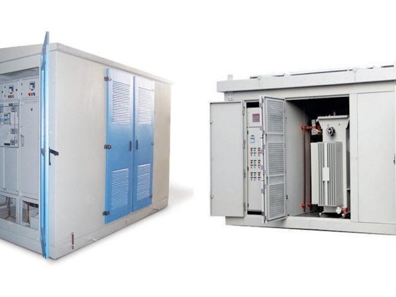
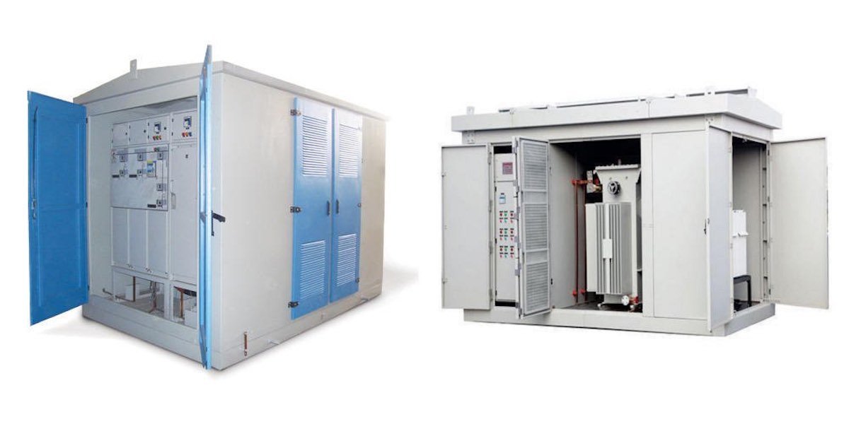
Outdoor compact substations combine MV switchgear, transformer and LV distribution in one enclosure. Protection and earthing are the most safety-critical parts of the design. Poor earthing causes dangerous touch voltages and equipment damage during faults. This guide covers the earthing and protection design requirements for outdoor compact substations. Start with the basics in our compact substation selection guide.

Why Earthing Is Critical in Compact Substations
A compact substation sits close to people and buildings. When a phase-to-earth fault occurs, fault current flows through the earth path. If the earthing system has high resistance, the enclosure and nearby ground rise to dangerous voltage. The design goal is to keep touch voltage and step voltage below safe limits for the fault clearing time.
Earthing System Design Requirements
1. Earthing grid or ring
Install a closed ring earth conductor around the substation base, connected to earth rods at corners. The grid should cover the full footprint, not just the enclosure corners.
2. Earth electrode resistance
Target an earth resistance of 4 ohms or less for most utilities, measured with a three-point fall-of-potential test. Rocky soil may require deeper rods or chemical earthing.
3. Enclosure bonding
Bond the enclosure, doors, cable glands, transformer tank and LV neutral to the earth bar with separate conductors. Do not rely on hinges or paint for continuity.
4. Touch and step voltage control
Use surface material with high resistivity (gravel layer) inside the fence and keep the earth grid mesh spacing small enough to limit step voltage.
Protection Design Requirements
MV protection
- Ring main unit with fuses for transformer protection.
- Overcurrent and earth fault relay when using a VCB.
- Lightning arrester on the MV cable termination.
LV protection
- Main LV breaker or switch fuse for the outgoing feeder.
- MCCB distribution for final circuits.
- RCD for personnel protection where required.
Surge protection
Install SPDs at the LV board to protect connected equipment from switching and lightning surges. See our protection wiring standards article for similar logic in solar projects.
Transformer Protection in Compact Substations
Distribution transformers inside compact substations need:
- High-voltage fuses sized to the transformer inrush.
- Low-voltage breaker with thermal and magnetic trips.
- Thermal protection with oil temperature alarm on larger units.
- Pressure relief device on oil-immersed transformers.
Cable Entry and IP Requirements
Cable entries must be sealed to prevent water ingress and vermin. Typical requirements:
| Area | Requirement |
|---|---|
| Enclosure ingress protection | IP34 minimum, IP54 recommended |
| Cable glands | IP68 for buried cable entries |
| Ventilation | Natural convection with rain hoods |
| Door opening angle | Min 90°, ideally 180° for access |
Earthing System Testing
Commissioning tests
- Earth resistance measurement.
- Continuity test of all bonds.
- Touch voltage measurement during earth fault simulation.
- Insulation resistance of MV and LV circuits.
Record the results and keep them with the substation documentation. The same test philosophy applies to our MV switchgear testing guide.
Common Design Mistakes
- Using the transformer tank as the only earth path.
- Painting over earth connection points.
- Missing a dedicated earth bar for all equipment bonding.
- Oversizing fuses beyond the cable or transformer rating.
- Ignoring soil resistivity before choosing the electrode design.
Earthing Material and Installation Practice
Use copper tape or stranded copper for the earthing conductor inside the substation, typically 25 x 3 mm tape or 50-70 mm2 stranded copper for a 630-1250 kVA compact substation. Steel galvanized tape can be used for the buried ring, but all exposed connections above ground should be copper to avoid corrosion at the junction.
Connection practice
- All earth connections must be bolted, not clamped over paint.
- Clean the contact surface and apply anti-oxidation compound.
- Use two bolts per connection where vibration is expected.
- Mark every earth point with the standard earth symbol.
- Keep the earthing bar accessible for testing without removing panels.
Bonding of doors and removable panels
Doors with electrical equipment must be bonded with a flexible copper braid. Hinges are not a reliable earth path, especially after years of painting and corrosion. The same rule applies to removable gland plates and access covers.
LV Distribution Board Integration
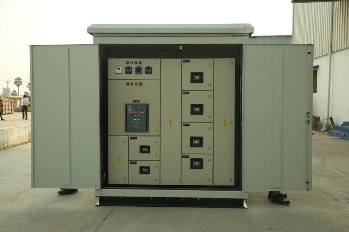
The LV section of a compact substation feeds the local network or a consumer installation. Good integration includes:
- A main incomer breaker with overcurrent and earth fault protection.
- Separate busbars for neutral and protective earth, bonded at one point.
- SPD at the LV incomer for surge protection of connected equipment.
- Clear phase identification and cable marking for safe maintenance.
- A metering compartment with CT terminals and sealing provision.
When the substation feeds solar or industrial loads, the protection coordination must be checked against the connected equipment. Our protection wiring standards article covers the DC and AC protection layers used in renewable projects.
FAQ
1. What is a safe earth resistance for a compact substation?
Most utilities specify 4 ohms or less. Verify with the local utility before design finalization.
2. Do I need a separate earth for lightning?
Lightning arresters connect to the main earthing system. A separate lightning earth can create dangerous potential differences and is generally avoided.
3. Why is a gravel layer placed around the substation?
Gravel has high resistivity, which reduces step voltage at the surface during faults.
4. How often should earthing be tested?
Annually, and after any major fault, lightning strike or earth disturbance.
5. Can the LV neutral and earth share a bar?
No. Keep neutral and protective earth separate in the LV distribution, and bond them at one defined point only.
6. What protection is mandatory for the transformer?
HV fuses and LV breaker are the minimum. Add thermal protection and pressure relief for larger oil-immersed units.
About Electric-GS
Electric-GS is a professional medium and low voltage switchgear manufacturer based in Yueqing, China. We supply ring main units, GIS, vacuum circuit breakers, LV and MV switchgear, transformers, compact substations and solar distribution products as an OEM/ODM factory. For a quotation or technical support, email info@electric-gs.com or contact us on WhatsApp at +86 135 8897 8050. Visit our partner sites electricgs.com and electric-cn.com for more product information.
3 thoughts