Why Power Factor Correction Matters for MV Networks
Many industrial plants pay for power they never use. Low power factor means more current, more losses and higher demand charges from the utility. A capacitor bank corrects the power factor, cuts reactive power, and lowers both energy and demand costs. Correct capacitor bank selection is the first step to a leaner, more reliable electrical system.
When a plant runs motors, transformers and welding equipment, the load becomes partly inductive. Inductive load draws reactive power that does no useful work but still loads the transformer and cables. Poor power factor can trigger utility penalties, cause voltage drop, and reduce the usable capacity of your switchgear and transformer. Installing a capacitor bank fixes all three problems at once.
The payoff is a lower monthly bill, more usable capacity from the same transformer, and steadier voltage for sensitive equipment. That is why power factor correction is one of the first upgrades most industrial plants make, and why proper capacitor bank selection matters so much.
How a Capacitor Bank Works
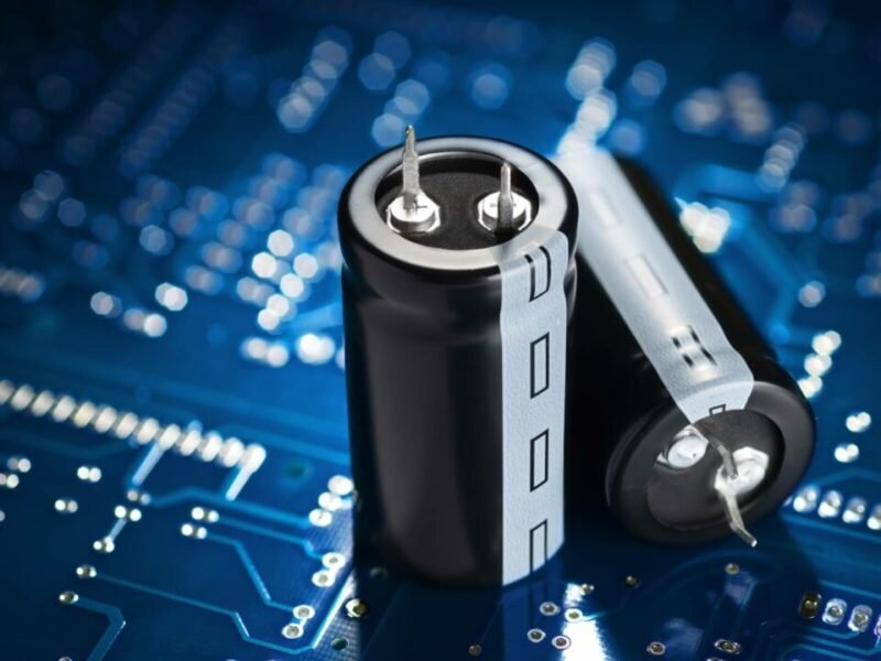
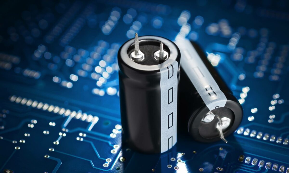
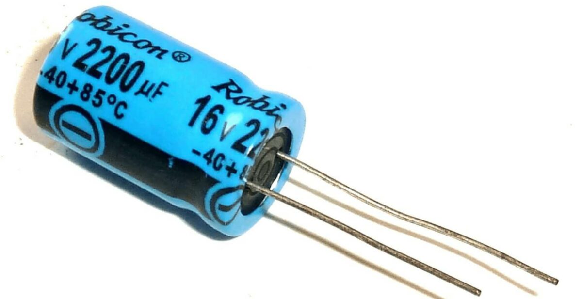
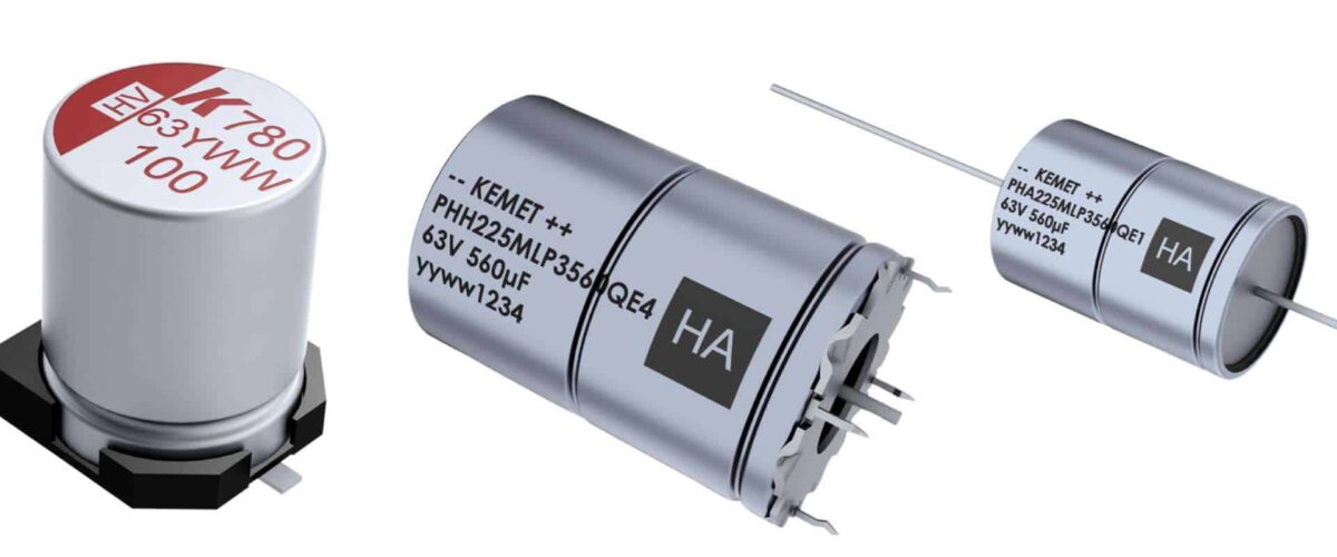
A capacitor bank is a set of capacitors connected in parallel, usually with switching and protection equipment. Each capacitor stores reactive energy and releases it the moment a motor or transformer needs it. This local supply keeps reactive power from flowing back through the utility meter.
Capacitor banks for medium voltage networks are built as metal-enclosed panels that match the layout of your existing switchgear, as described in the 12kV MV switchgear panel guide. The core components are shown below.
| Component | Function |
|---|---|
| Capacitor units | Store and release reactive power |
| Discharge resistors | Safe discharge after disconnection |
| Contactors or breakers | Step switching on and off |
| Detuned reactors | Protect capacitors against harmonics |
| Control relay | Automatic switching by power factor |
| Fuses and earthing | Overcurrent and safety protection |
6-Step Capacitor Bank Selection
Follow this capacitor bank selection process to avoid oversizing, undersizing and damage from harmonics.
Step 1. Measure the current power factor. Use a power analyser on the main incomer over a full working cycle. Record the average and the worst-case value, because night and peak load differ.
Step 2. Define the target power factor. Utilities usually set the tariff threshold at 0.90 to 0.95. Confirm your supplier target before you size the bank.
Step 3. Calculate the required kvar. Use the formula in the sizing section below. This gives the total reactive power you need to install.
Step 4. Choose fixed or automatic. Stable, continuous loads suit a fixed bank. Variable loads need automatic steps controlled by a relay.
Step 5. Check voltage and harmonics. Confirm the bank voltage rating matches the network and decide whether detuned reactors are needed.
Step 6. Select the enclosure and protection. Choose the panel, breaker, fuses and earthing that fit your plant, following the low voltage switchgear guide for LV duty.
Fixed vs Automatic Capacitor Bank
The right choice depends on how stable your load is. A fixed bank is simple and cheap but can over-compensate at light load. An automatic bank switches steps as the load changes and keeps the power factor near the target all day.
| Feature | Fixed Bank | Automatic Bank |
|---|---|---|
| First cost | Lower | Higher |
| Switching | Manual or fixed | Automatic steps |
| Best for | Stable continuous load | Variable load |
| Harmonics risk | Can be managed | Lower with reactors |
| Control | Simple | Power factor relay |
Sizing Calculation for a Capacitor Bank
Use the standard formula to size the bank. Qc = P × (tan φ1 − tan φ2), where P is the active load in kW, φ1 is the present power factor angle and φ2 is the target power factor angle.
Example. A plant has an active load of 800 kW and a power factor of 0.70. The target is 0.95. The tangent of 0.70 is 1.02 and the tangent of 0.95 is 0.33. The required reactive power is 800 × (1.02 − 0.33) = 552 kvar. In practice you round up and install a bank of about 600 kvar to allow for tolerances and future growth.
Always size against the real load profile, not the nameplate, and add a small margin of 5 to 10 percent. If your network carries many variable-frequency drives, include detuned reactors to stop harmonic currents from damaging the capacitors.
Installation, Protection and Safety
Install the bank close to the inductive load to minimise reactive current in the cables, and feed it through a dedicated breaker. Provide overcurrent and overvoltage protection, proper discharge resistors, and reliable earthing as covered in the substation earthing design guide.
Safety is essential because capacitors hold charge after disconnection. Never touch terminals until the discharge time has elapsed. Use approved discharge resistors and verify zero voltage before any maintenance. A good bank integrates cleanly with your main distribution board guide and higher-voltage panels such as the 40.5kV switchgear guide, so plan the interconnection when you upgrade.
FAQ
What power factor should I target?
Most utilities require 0.90 to 0.95. Confirm the tariff threshold with your supplier before sizing.
How do I know if my plant needs a capacitor bank?
If your utility bill shows low power factor, a penalty charge, or your transformer is near capacity, a capacitor bank will usually help.
Should I choose a fixed or automatic bank?
Fixed suits stable loads; automatic suits variable loads because it switches steps to keep the power factor near the target.
Can a capacitor bank damage my switchgear?
Only if it is wrongly sized or unprotected. Correct selection, detuned reactors and proper protection prevent resonance and overvoltage.
How long is the payback period?
For most industrial plants the payback is between 6 and 18 months, depending on the tariff and load profile.
Can Electric-GS supply a custom capacitor bank?
Yes. Electric-GS designs and builds capacitor banks and power factor correction panels as part of its switchgear OEM and ODM service.
Electric-GS — Your Switchgear OEM Partner. Electric-GS is a switchgear manufacturer based in Yueqing, China. We supply ring main units, MV switchgear, vacuum circuit breakers, transformers, capacitor banks and solar power distribution equipment. Our factory supports OEM and ODM projects with full type tests and a solid track record.
Contact us for a tailored quotation: email info@electric-gs.com or WhatsApp +86 135 8897 8050.