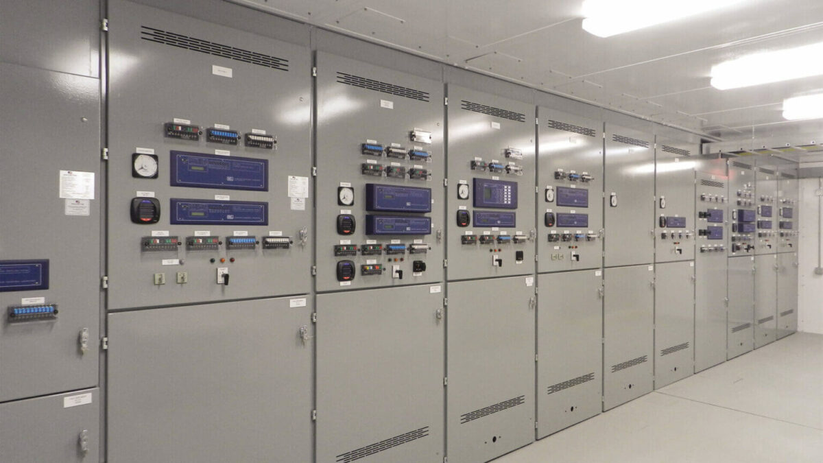
Partial Discharge Testing: 6 Checks Before Switchgear Ships
Most medium voltage failures start small. A void inside cast resin, a sharp point on a busbar, a loose screen connection — none of them show up on a routine insulation resistance reading. They show up as partial discharge, a tiny internal spark that eats insulation a few molecules at a time. A proper partial discharge test is the only routine check that catches these defects before the breaker, ring main unit or GIS leaves the factory.
What Partial Discharge Really Tells You
Partial discharge is a localised electrical breakdown that does not bridge the whole insulation gap. It happens in voids, at metal-to-insulation interfaces, along contaminated surfaces and at floating metal parts. Each event is measured in picocoulombs (pC), and the value is a symptom, not a diagnosis: 20 pC in a solid epoxy barrier is serious, while 20 pC picked up from a test lead is often noise.
That is why a bare number on a datasheet proves very little. What matters is where the coupler sat, which method was used, how the background noise was measured, and whether the reading stayed stable during a one-minute hold at 1.2 times rated voltage.
The Four Methods You Should Recognise
Partial discharge test on gas insulated switchgear assembly
Every lab claims to “do PD testing”. Ask which method, because sensitivity and blind spots differ sharply.
Method
Typical sensitivity
Best for
Main limitation
IEC 60270 conventional
2–5 pC
Factory type and routine tests on complete equipment
Needs shielded room; heavy setup
UHF (300 MHz–1.5 GHz)
Equivalent to a few pC in GIS
GIS compartments, on-site commissioning
No calibrated pC value; trend only
Transient earth voltage (TEV)
Roughly 10–20 pC
Quick scan of LV and MV panel surfaces
Poor inside solid insulation
Ultrasonic / acoustic
Surface and tracking defects
Locating the source once PD is detected
Blocked by enclosed tank walls
For a 12 kV RMU or a 24 kV metal-clad panel, the conventional method remains the reference. UHF is a useful cross-check inside a sealed tank, and ultrasonic is how you find the exact compartment afterwards.
Reading pC Values Without Guessing
Metal clad switchgear panel prepared for partial discharge test
IEC 62271-200 and IEC 62271-100 both point to the same logic: at 1.2 times rated voltage, measured PD should stay below the agreed limit, and it must not rise sharply during the hold. A common factory limit for cast resin equipment is 10 pC at 1.2 Ur, while some utilities accept 20 pC for assembled panels. The limit must be written into the purchase specification, otherwise the supplier picks the easier number.
Two more numbers belong in the report: the background noise level before the test (it must be at least half the limit, ideally under 2 pC) and the PD inception and extinction voltages. A unit that starts discharging at 0.8 Ur and stops at 0.6 Ur has a defect that will grow in service, even if it squeaked under the limit at 1.2 Ur.
Setup Mistakes That Fake a Pass
Vacuum circuit breaker pole ready for partial discharge measurement
PD testing is easy to do badly. The failures below account for most “passing” units that fail in the field.
Unfiltered supply. A test transformer that feeds from a dirty mains supply injects noise straight into the measuring circuit.
Long, unshielded leads. Every extra metre of cable adds capacitance and picks up ambient interference.
Testing at too low a voltage. Defects that only appear above 1.2 Ur are missed entirely.
No stabilisation time. Readings taken five seconds after energising are still settling; hold for at least one minute.
Coupler on the wrong terminal. On a three-phase unit, one phase at a time, with the other phases earthed, or the result means nothing.
Ask for the raw phase-by-phase chart, not a summary table. A genuine report shows the noise trace, the applied voltage and the phase-resolved pattern.
Shop Test Versus Site Test
Factory testing happens in a shielded room with a stable supply and a known background. Site testing happens next to inverters, VFDs and mobile phones, and the background can easily sit above the defect you are looking for. That is why on-site work is judged on trend and phase pattern rather than an absolute pC figure.
If a unit passed at the factory and shows activity on site, the cause is usually moisture, a loose stress cone, a damaged screen or a contaminated bushing — not the insulation itself. Clean and re-terminate before condemning the equipment.
A Buyer Checklist for PD Test Evidence
Before you sign the factory acceptance test, confirm these six items are in the package:
Method stated, with the standard number (IEC 60270 measurement, IEC 62271-200 limits).
Background noise recorded before the unit was energised.
Phase-by-phase readings at 1.1 Ur and 1.2 Ur, held one minute each.
Inception and extinction voltages recorded.
Calibration certificate for the coupler and the calibrator, dated within twelve months.
Serial numbers matching the units actually shipped, not the type-test sample.
Skip it and you may end up with switchgear that hums quietly for two years, then trips a feeder at the worst moment. The test takes twenty minutes per unit.
Frequently Asked Questions
What is a good partial discharge value for 12 kV switchgear? Below 10 pC at 1.2 times rated voltage is the usual factory target for cast resin parts. Assembled panels are sometimes accepted at 20 pC, but the limit should be agreed in writing before production.
Can partial discharge be measured without a shielded room? Yes, with UHF or TEV methods, but the result becomes a trend reading rather than a calibrated pC figure. Use it for screening and comparison, not for acceptance against a pC limit.
Does a passing PD test guarantee no failure? No. It proves the insulation was sound on the day of the test. Moisture ingress, loose terminations and cable damage can create new defects later, which is why repeat scans at commissioning and after five years matter.
How long does the test take? About twenty to thirty minutes per unit once the circuit is set up, including the one-minute holds at 1.1 and 1.2 Ur. Setup and calibration usually take longer than the measurement.
Why do readings rise during the hold? A rising trace points to a defect that is being eroded by the discharge itself — typically a void or a floating particle. Stop the test and investigate; do not average the number down.
Is PD testing required for GIS? It is effectively mandatory. Sealed-for-life compartments cannot be inspected later, so the factory PD scan plus UHF sensors installed at commissioning are the only practical early warning you will get.
About the manufacturer. Electric-GS is an OEM/ODM switchgear factory based in Yueqing, China, producing ring main units, gas-insulated switchgear up to 33 kV, vacuum circuit breakers and LV/MV assemblies. Every unit is routine-tested with a recorded partial discharge scan before packing. For drawings, test reports or a quotation, write to info@electric-gs.com or reach us on WhatsApp at +86 135 8897 8050. Related reading: temperature rise test limits, nameplate ratings, GIS versus AIS and clearance and creepage. Our sister sites: electricgs.com and electric-cn.com.