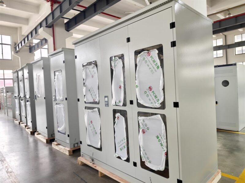
Busbar sizing is the decision that quietly fixes the cost, the temperature rise and the short-circuit withstand of every low-voltage panel. It is also the step most often copied from a previous project. This guide walks through the six checks a fabricator should close before cutting copper.
In an LV assembly, the busbar is the only component that carries current through every section. A bar that is 10 mm too narrow raises the temperature rise above the IEC 61439 limit; a bar that is 1 mm too thin fails the short-time withstand test. Neither problem appears until the panel is assembled and tested, which is the worst moment to discover it.
The six checks below run in the order a fabricator can act on them: current first, then fault current, then joints, then clearances, then temperature, then records.
Check 1: continuous current with real ambient derating
Start from the design current of the outgoing ways, not from the incoming breaker rating. Add the diversity factor the client actually operates with, then apply the ambient correction for the enclosure.
| Condition | Typical derating | Effect on a 400 A bar |
|---|---|---|
| 35 °C inside the enclosure | 1.00 | 400 A |
| 45 °C inside the enclosure | 0.90 | 360 A |
| 55 °C inside the enclosure | 0.80 | 320 A |
| Bars mounted vertically, no ventilation | 0.85-0.90 | 340-360 A |
A 400 A bar in a 55 °C enclosure is a 320 A bar. Sizing by the nameplate current alone is how panels pass the factory test and fail in a tropical plant room.
Check 2: short-time withstand current and duration
The busbar must survive the prospective fault current for the stated time, usually 25 kA for 1 s or 50 kA for 1 s in LV assemblies. The mechanical force between two bars during a fault rises with the square of the current, so a joint that holds at 25 kA can be torn apart at 50 kA even when the copper section looks adequate.
Two numbers belong in the specification: the current and the duration. A bar rated for 1 s is not automatically good for 3 s; the thermal duty is the product of both.
Check 3: joint resistance and surface treatment
Every joint is a heat source. A bolted joint with the wrong torque or an oxidised surface adds resistance, and resistance at 400 A becomes heat at the next busbar. Tin plating is standard for indoor panels; bare copper is acceptable only when the environment is dry and the joint is re-treated after assembly.
- Torque to the joint schedule and mark the bolts after tightening.
- Clean and neutralise the surface before plating; oxide left under tin becomes a hot spot.
- Keep joint resistance below 1.2 times the equivalent bar section, measured across the joint.
Check 4: support spacing and clearance
Support spacing decides the mechanical resonance of the bar and the clearance to the enclosure. A bar that is correctly sized electrically can still fail a short-circuit test because the supports are too far apart and the bar touches the frame under fault force.
Clearance and creepage follow the pollution degree of the installation; the same bar in a clean workshop and a coastal plant needs different distances. For the distance rules, see our guide on clearance and creepage distance.
Check 5: temperature rise against IEC 61439 limits
The limit is not the busbar temperature; it is the rise above ambient at the terminals and at the accessible surfaces. Typical verification limits are 70 K for bare copper and 65 K for insulated bars, measured after the assembly reaches steady state.
| Part | Limit (K) | How it is verified |
|---|---|---|
| Busbar, bare copper | 70 | Thermocouple at the joint and mid-span |
| Busbar, insulated | 65 | Thermocouple on the insulation surface |
| Terminals for external cables | 70 | Thermocouple at the cable connection |
| Accessible enclosure surface | 30 (metal), 40 (insulating) | Surface probe after steady state |
If a prototype is not built, the calculation route in IEC 61439-1 allows a designer to prove the rise by comparable design. That route requires the records to be kept, which is the sixth check.
Check 6: fabrication and test records
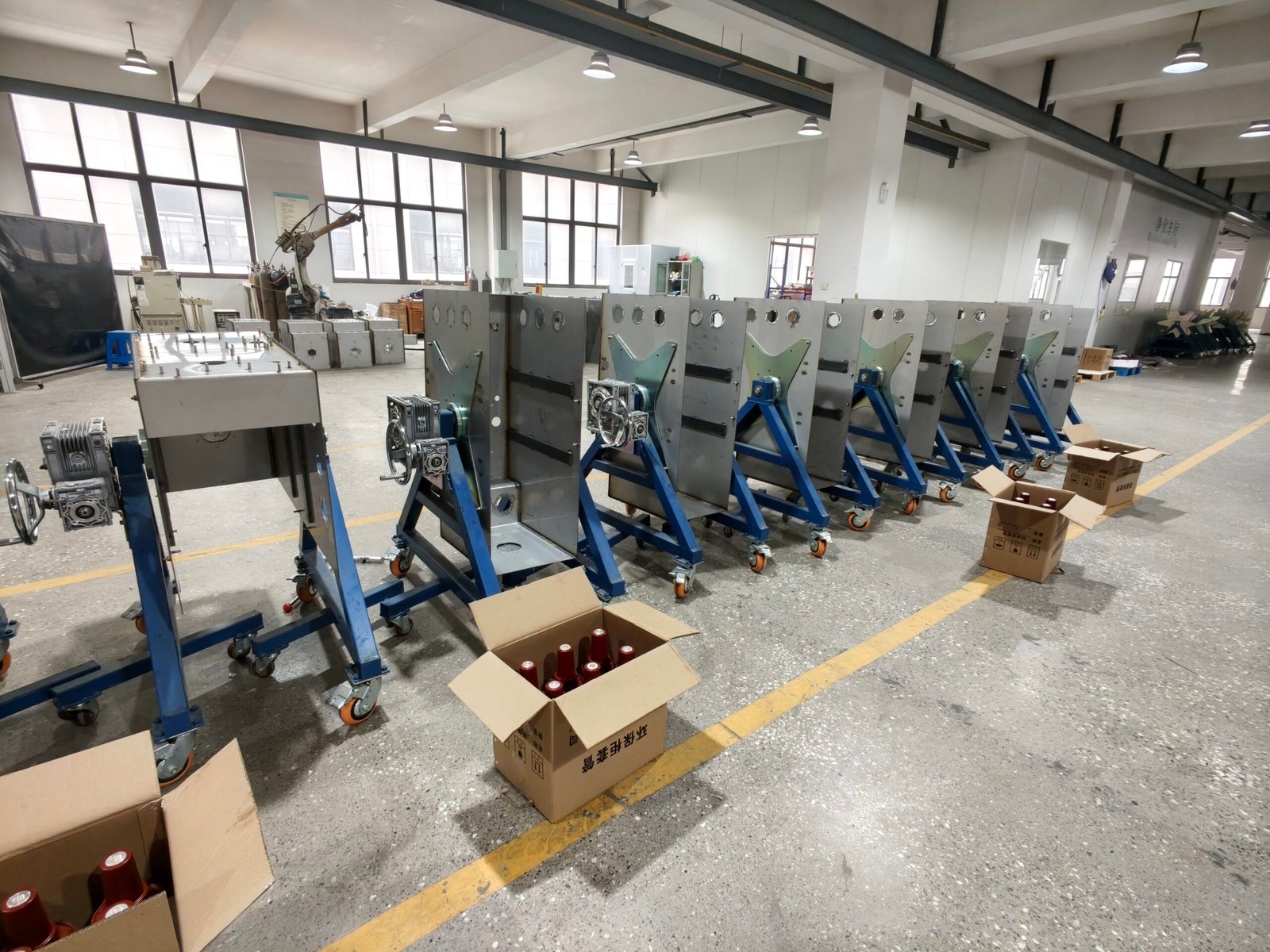
Sizing is only complete when the workshop holds the evidence: the bar drawing with section and material, the joint torque record, the plating certificate, the support layout and the temperature rise result. Without them, a panel that passes today cannot be defended in a dispute or reproduced in a repeat order. Our notes on temperature rise testing show what the record should contain.
For medium-voltage assemblies and MV panels, see our sister site ElectricGS; component-level selection notes sit on electric-cn.com.
For the jointing step that follows sizing, see busbar jointing in six steps. If the panel is a Form 3b or Form 4 assembly, the bar route also depends on the separation, covered in LV switchgear form of separation.
FAQ
Q: How do I choose the busbar section for 400 A?
A 400 A continuous duty is normally met by a 30 x 10 mm copper bar in a ventilated enclosure at 35 °C. At 55 °C, step up to 40 x 10 mm or accept the derated current. Always check the fault level before fixing the section.
Q: Is aluminium acceptable for LV busbars?
Yes, where the assembly is designed for it and the joints are bimetallic or transitioned. Aluminium needs a larger section for the same current and a different joint treatment; mixing materials without a transition joint is the usual failure.
Q: What is the difference between busbar sizing and busbar jointing?
Sizing fixes the section, material and support spacing. Jointing fixes how the bars are connected and torqued. A well-sized bar with a poor joint overheats at the joint, not in the middle.
Q: Does a higher fault rating mean a thicker bar?
Not only thicker. The support spacing, the joint strength and the bar’s own stiffness matter as much as the section, because the fault force is mechanical before it is thermal.
Q: How is temperature rise proven without a prototype?
IEC 61439-1 allows a calculation or comparison route when a tested reference design exists. The designer must document the comparison and keep it with the assembly verification file.
Q: Can busbar sizing be changed after the panel is built?
Rarely in practice. The bar, supports and cable terminals are fixed by the enclosure layout, so a change after fabrication usually means a new internal assembly rather than a modification.
About the manufacturer. Electric-GS is an OEM/ODM switchgear factory in Yueqing, Zhejiang, China. We build LV and MV assemblies, ring main units, GIS, vacuum circuit breakers, load break switches, transformers, kiosk substations and solar combiner boxes, with fabrication drawings, joint torque records and routine test sheets supplied per order.
Send your single-line diagram, fault level and ambient conditions to info@electric-gs.com or WhatsApp +86 135 8897 8050 for a busbar and enclosure proposal within 24 hours.