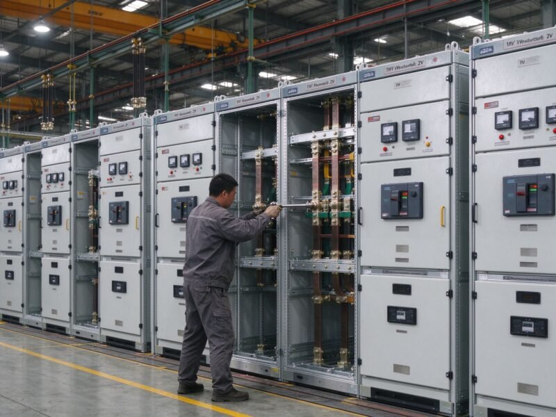
A motor control center (MCC) is a centralized panel that groups motor starters, variable frequency drives (VFDs), soft starters and protective devices for an industrial plant into one enclosure. It receives power from the main distribution board, controls every connected motor, and protects each starter with its own breaker, contactor and overload relay. One MCC can manage dozens of motors from a single location.
This guide covers what an MCC is, which components sit inside it, how to design one, and how to avoid the most common faults.
What Is a Motor Control Center (MCC)?
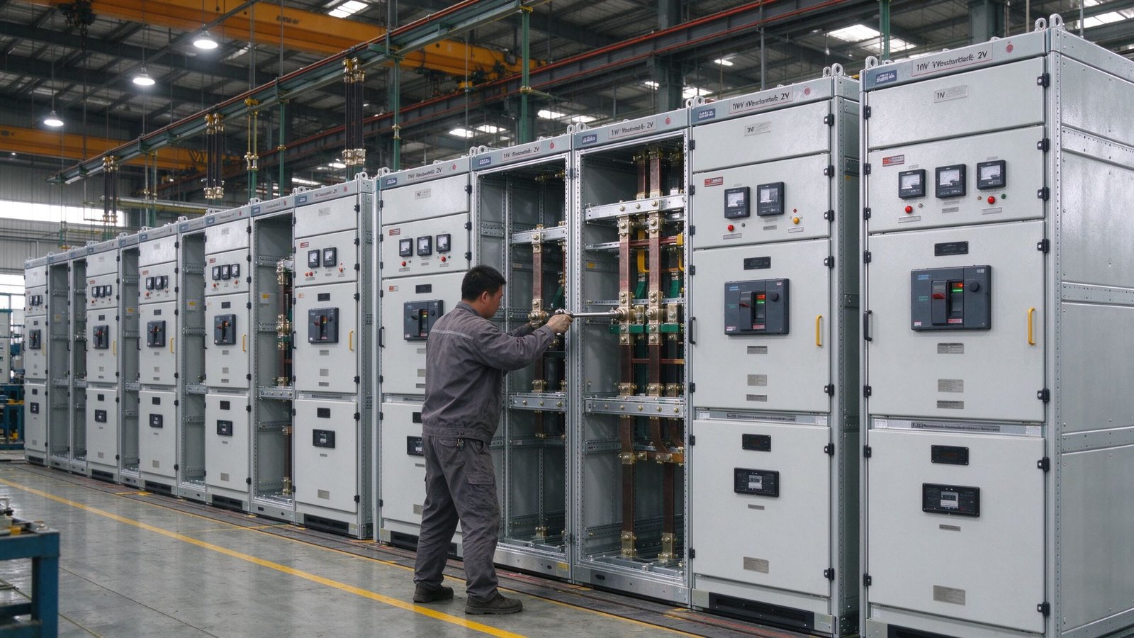
An MCC is a factory-assembled enclosure with multiple starter units mounted on a common bus. Each unit is a removable bucket or compartment that contains the control and protection devices for one motor. The MCC brings the motor supply, control circuits and instrumentation together in one place, so operators do not need to walk to every motor when they start or stop a machine.
Typical applications are pumps, fans, conveyors, compressors, crushers and machine tools. The MCC is the standard solution in water treatment plants, cement plants, textile mills, food processing lines and HVAC systems, where many motors must run with coordinated control and protection.
Key Components of an MCC
Every motor control center combines the same basic building blocks. Knowing each component helps you read the drawings and order the right spare parts.
- Incoming bus: copper or aluminium bars that feed all starter units.
- Main breaker or switch: isolates the whole MCC for safe maintenance.
- Starter units: contactor, overload relay and fuses or breakers per motor.
- VFD and soft starter cells: speed control and reduced starting current.
- Control transformer: supplies 110V or 230V control circuits.
- PLC and relays: sequence logic, interlocks and remote control.
- Metering: ammeters, kWh meters and status indicators.
- Enclosure: usually IP42, IP54 or IP55 steel cubicles.
Types of Motor Control Centers
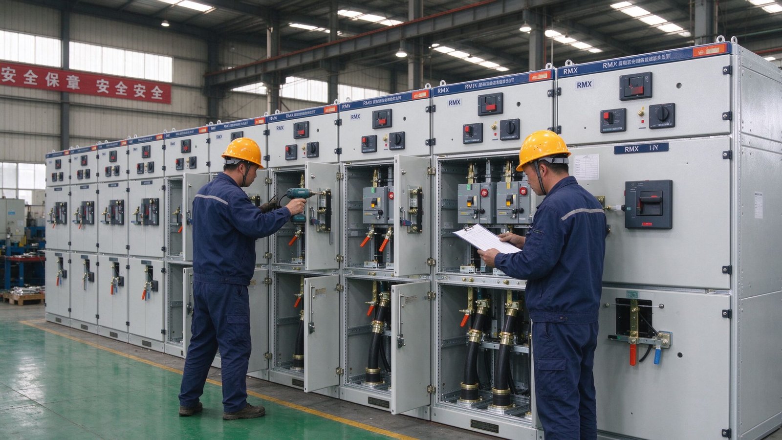
MCCs are classified by the control technology and by the design standard. The table below compares conventional and intelligent units.
| Feature | Conventional MCC | Intelligent MCC |
|---|---|---|
| Control | push buttons and contactors | PLC, VFDs and fieldbus |
| Wiring | point-to-point wiring | networked control cabling |
| Monitoring | lamps and local meters | remote SCADA and logging |
| Maintenance | manual inspection | predictive diagnostics |
| Cost | lower first cost | lower lifecycle cost |
On the standard side, NEMA MCCs follow the US practice with large horsepower starters, while IEC MCCs use compact modular units and are more common in Europe, Asia and the Middle East. Most export projects follow IEC 61439-2, which is the assembly standard for low voltage switchgear and controlgear.
How to Design an MCC: 7 Practical Rules
Follow these rules during design. Changes after fabrication are expensive and delay the project.
| Rule | Design action | Common mistake |
|---|---|---|
| 1. List every motor | Record kW, rated current, start method and duty | Missing standby or future motors |
| 2. Group by duty | Separate critical, standby and intermittent loads | Mixing process and non-process units |
| 3. Choose the start method | DOL, star-delta, soft starter or VFD per motor | Oversized contactors or unstable starts |
| 4. Check coordination | Match breaker, contactor and overload classes | Type 1 coordination on critical drives |
| 5. Plan the bus rating | Size for peak demand, not nameplate sum | Undersized busbar and temperature rise |
| 6. Add spare cells | Reserve 15-20% empty buckets | No space for plant expansion |
| 7. Design the control circuit | Draw the ladder logic before panel build | Field changes during commissioning |
An MCC is always fed from the main low voltage point. Compare this with the main distribution board design, where the busbar and discrimination rules decide how many feeders the plant can support. The same upstream logic applies to the dry type transformer that feeds the plant and to the distribution transformer sizing of the site.
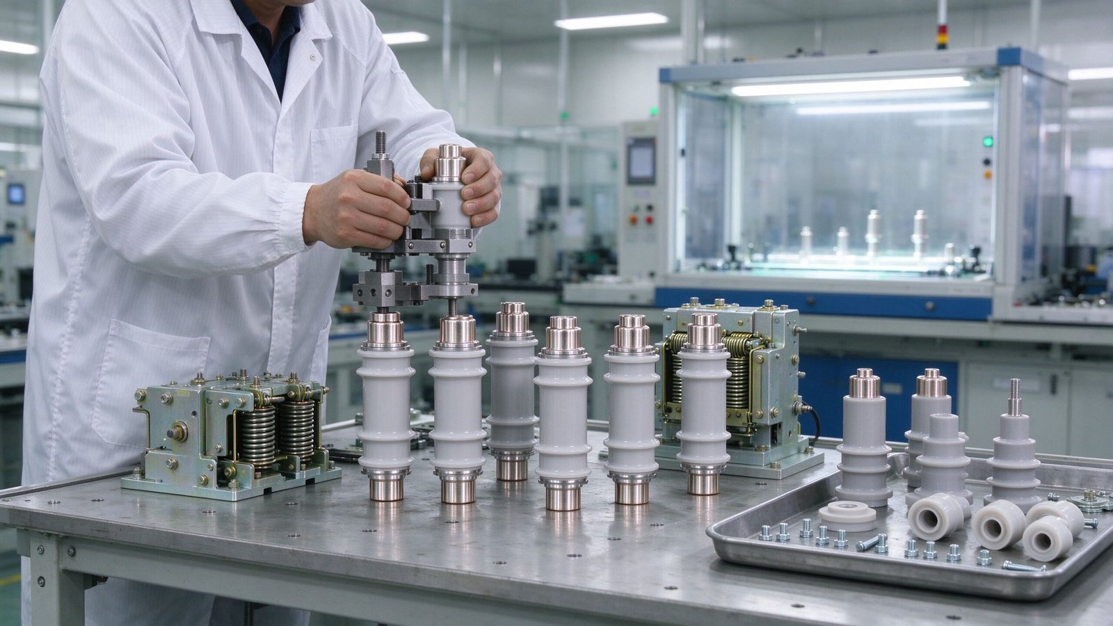
Site teams often compare an MCC with individual motor starters mounted near each machine. The table below makes the difference clear.
| Item | Individual starter | Motor control center |
|---|---|---|
| Installation | wiring done at each motor | factory-built panel |
| Space | spread across the plant | compact central area |
| Safety | limited coordination | locked and coordinated units |
| Expansion | hard to extend | spare cells available |
| Fault handling | local only | group protection and metering |
Installation and Safety Requirements
Installation quality decides the service life of the MCC. The panel must stand on a solid frame, be levelled and have a clean earth connection. Cables enter through the top or bottom gland plates, with enough spare capacity for future feeders. The phase sequence and motor numbers must be marked at both ends.
Safety follows IEC 61439-2 and the local wiring rules. Key points are a visible main isolating switch, an interlock that opens the door only when the unit is isolated, arc fault containment for high fault levels, and clear working clearance in front of the panel. Maintenance staff must be trained to check the arc flash label before opening any cell.
Common MCC Problems and Maintenance
Most MCC failures start with heat and contact wear. A thermographic survey once a year finds hot spots before they become failures.
- Loose busbar joints: retighten and measure contact resistance.
- Contactor wear: check contacts and coils during each shutdown.
- Overload nuisance trips: verify the setting against the real motor current.
- Dust and moisture: keep the enclosure sealed and clean filters.
- Old starters: replace contactors after the maker lifetime figure.
MCC FAQ
1. What is a motor control center (MCC)?
An MCC is a centralized panel that groups the starters, drives and protection devices for many motors in one enclosure, fed from a common busbar.
2. What is the difference between an MCC and a main distribution board?
The MDB distributes raw power to all feeders, while the MCC specifically controls and protects motors, adding contactors, overload relays and speed drives.
3. What components are inside a motor control center?
A main incoming switch, busbars, starter units with contactor and overload relay, VFD or soft starter cells, a control transformer, PLC logic and metering.
4. How do I size a motor control center?
List every motor with its rated current and start method, apply the diversity factor, add 15-20% spare cells, then check the bus rating and fault level.
5. What are the safety requirements for MCC installation?
Follow IEC 61439-2, provide a visible isolator, door interlocks, arc fault containment where needed and correct working clearance for operators.
6. Can an MCC include variable frequency drives?
Yes. VFD cells are standard options in modern MCCs, giving soft starting, speed control and energy savings for pumps, fans and conveyors.
About Electric-GS
Electric-GS is a professional OEM and ODM manufacturer based in Yueqing, China, focused on ring main units, switchgear, transformers and distribution equipment. We build motor control centers and complete low voltage solutions for projects worldwide. For a quote or a technical drawing, email info@electric-gs.com or contact us on WhatsApp at +86 135 8897 8050. Compare our medium voltage range at electricgs.com and the Chinese technical library at electric-cn.com.
One thought