Inside a 33kV GIS Manufacturing Line
Gas insulated switchgear (GIS) for 33kV networks is built through a strict series of assembly and quality control steps. Every step protects the performance of the unit in the field. In this article we look at the first half of the 33kV gis manufacturing process: busbar assembly, insulation fixing, and main circuit resistance measurement.
This is the core of the switchgear. If the conductor and insulation work is wrong, no later test can fully correct it. So the factory gives these steps maximum attention.
Each panel follows a documented route card. The route card lists every operation, the tools to use, the torque values, and the person responsible. When a step is finished, it is signed off. This traceability is what allows a manufacturer to guarantee quality on every single unit.
Step 1: Copper Busbar Assembly
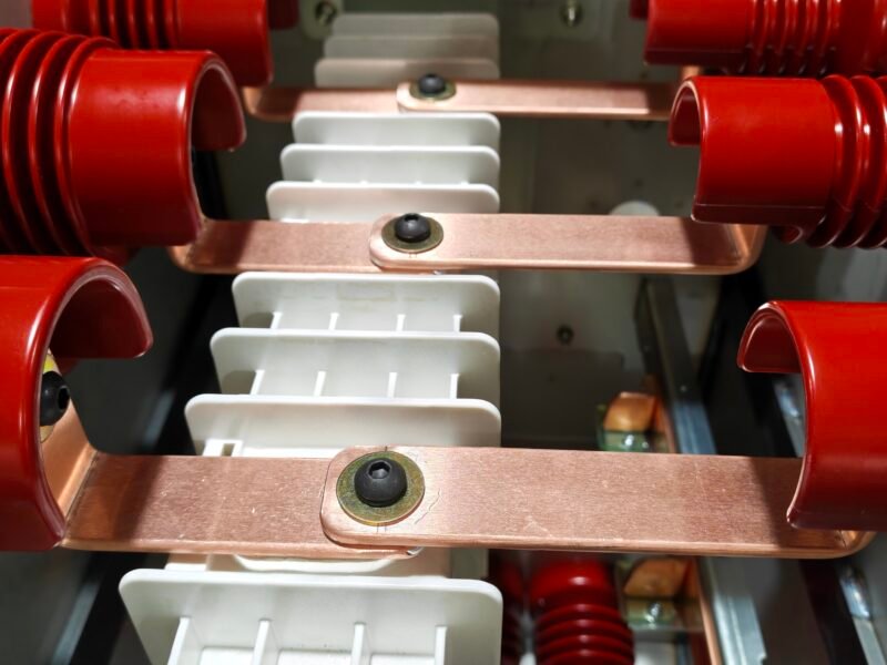
Busbars carry the main current inside the GIS panel. In the picture below you can see three parallel copper busbars fixed with bolts. The factory uses high-conductivity copper to keep resistance low and heat under control.
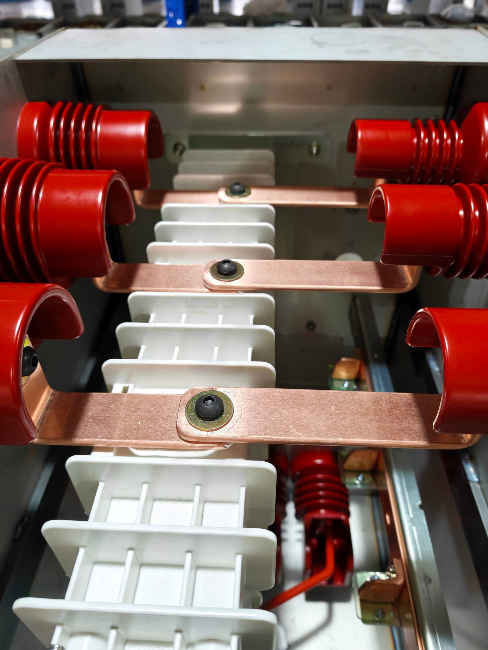
During assembly, workers clean every contact surface. They apply the correct torque to every bolt. This prevents loose joints and hot spots under full load. Busbars are sized for the rated current and short circuit withstand level of the panel.
Several checks happen before a busbar is accepted into the panel. The surface finish is inspected for scratches and oxidation. The dimensions are checked against the drawing. And the bolt torque is applied with a calibrated torque wrench, not by feel. A loose joint can create a hot spot that slowly damages the insulator over time. This attention to detail is what separates a reliable panel from one that fails early in service.
| Parameter | Typical 33kV GIS Value |
|---|---|
| Rated voltage | 33 kV |
| Rated normal current | 630 A – 2500 A |
| Short circuit withstand | 25 kA / 3 s |
| Busbar material | High conductivity copper |
| Main circuit resistance | Low mΩ range per phase |
Step 2: Insulator and Support Assembly
Insulators hold the busbars in position and keep the correct clearance between phases and to earth. The photo below shows white insulation supports fixed with metal bolts inside the panel.
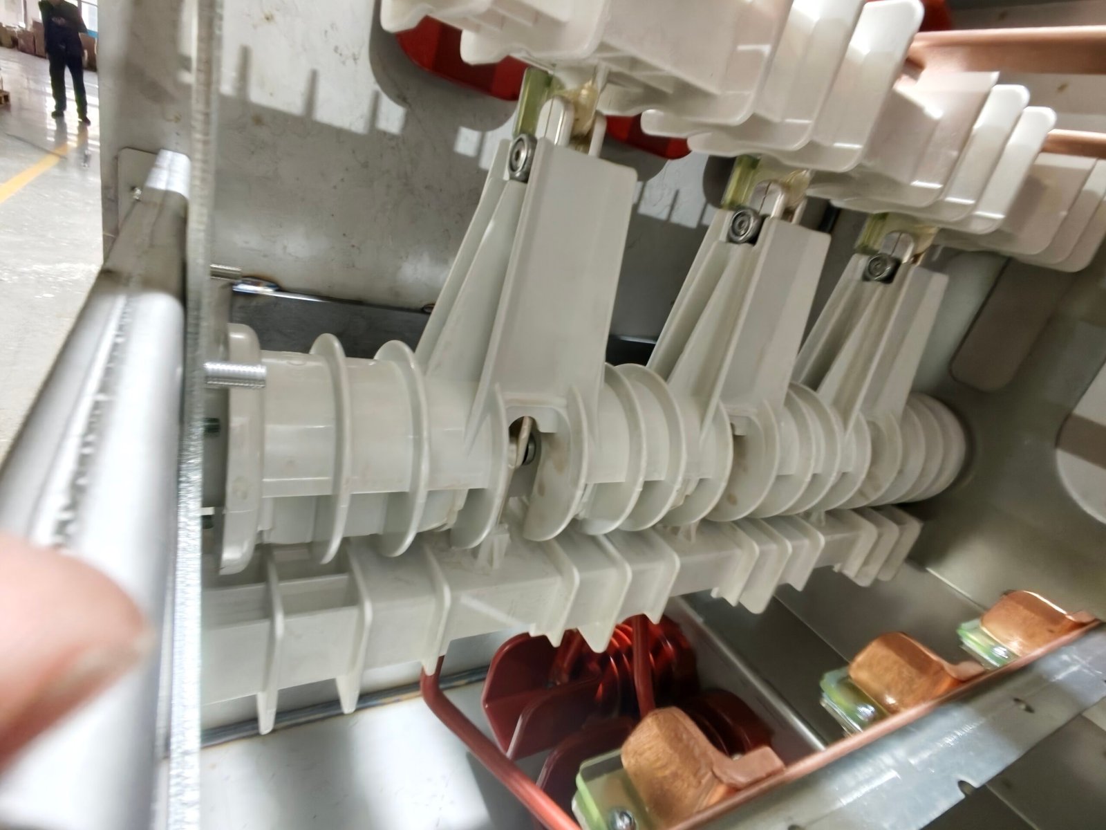
Each insulator is checked for cracks and surface damage before installation. The bolts are tightened to a controlled torque. Correct insulation work prevents flashover and partial discharge during operation.
Insulation is the most critical element for high voltage performance. Even a small surface scratch can become the start point of partial discharge. For this reason, workers handle insulators with clean gloves, store them in protected racks, and inspect each one under good light before assembly.
The clearance between phase and phase, and between phase and earth, follows the standard for the rated voltage. Too little clearance causes flashover. The insulator geometry is designed to keep this clearance safe even under surge voltage. Every insulator is also checked for correct orientation so the creepage distance is maintained in all three phases.
Step 3: Main Circuit Resistance Measurement
After assembly, the factory measures the main circuit resistance. The picture shows a tester connected to the busbar, with the result label showing a cold resistance of 27 mΩ per phase.
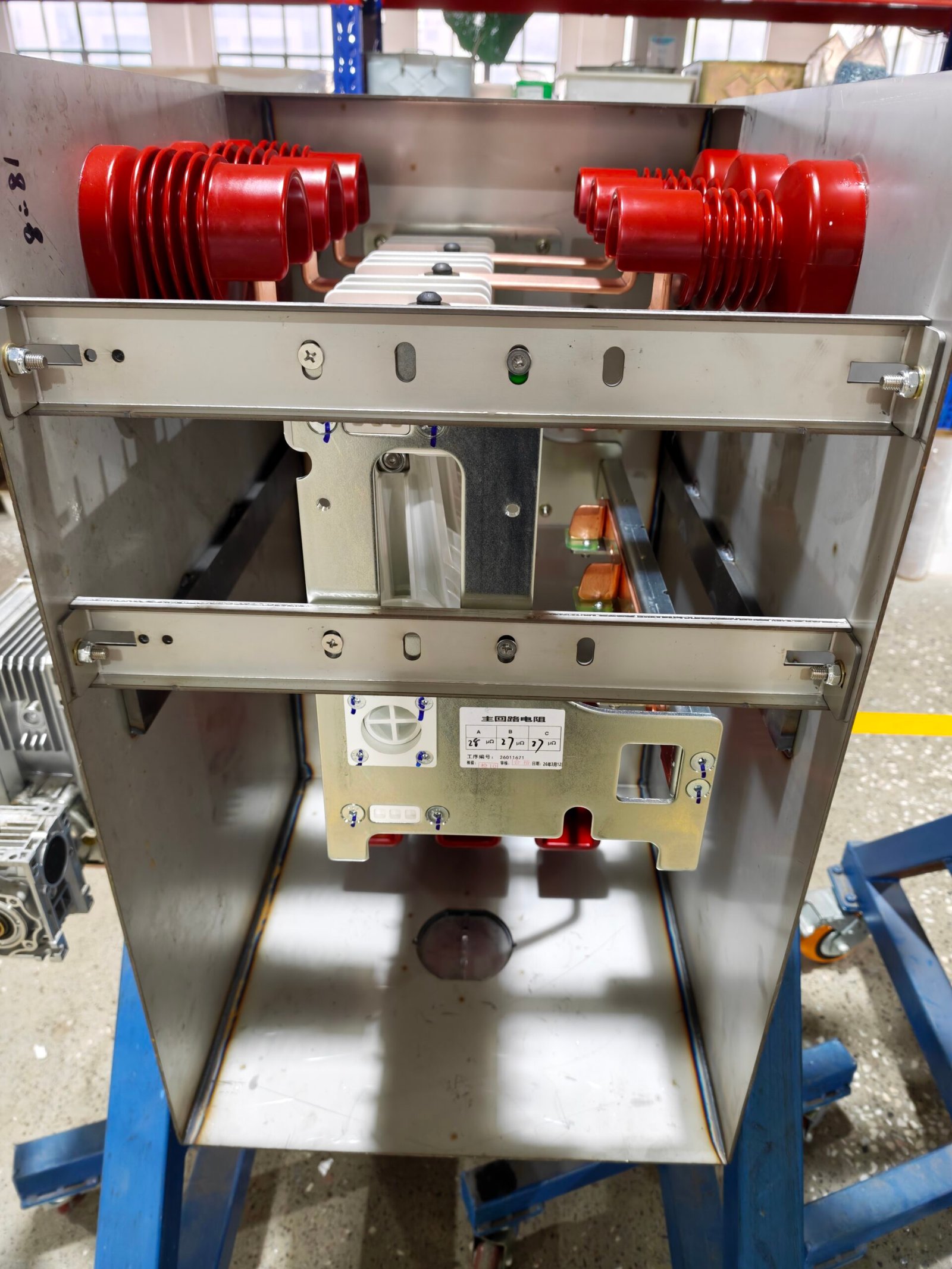
This test verifies that all connections are tight. A high resistance means a bad joint that will overheat. The measured value is recorded against the factory standard and kept in the quality file for every unit.
The measurement uses a sensitive micro-ohmmeter. The value is compared with the design limit for the panel. If the value is higher than the limit, the assembly team re-tightens the suspect joints and measures again until the value passes. This gives the customer confidence that the unit will run cool under full load.
- Clean every contact surface before bolting.
- Tighten all bolts to the specified torque.
- Measure and record main circuit resistance.
- Confirm resistance is below the factory limit.
- Sign off each step in the quality record.
Why These Steps Matter for Reliability
Busbar assembly and insulation are the backbone of reliable 33kV GIS. Loose connections cause hot spots. Weak insulation causes partial discharge and failures. The resistance measurement catches both problems before the unit ships.
This is why a responsible gis manufacturer invests in skilled workers, controlled torque tools, and a documented quality record for every panel.
The assembly bay is also kept clean and controlled. Dust and moisture are the enemies of high voltage insulation. Working on a clean bench, with clean tools and dry hands, reduces the risk of contamination that could later appear as partial discharge in service.
These first steps also set the stage for the rest of the production line. Once the busbar and insulation are correct, the vacuum interrupter, operating mechanism, and gas system can be assembled on a solid foundation. A panel that starts correctly is much more likely to pass the final high voltage tests.
FAQ
What is 33kV GIS?
33kV GIS is gas insulated switchgear designed for 33kV distribution networks, using SF6 or eco gas for insulation and arc interruption.
Why measure main circuit resistance in GIS?
It checks that all busbar and contact connections are tight, preventing overheating and failure under load.
What material is used for GIS busbars?
High conductivity copper is the standard material for GIS busbars.
What is a normal main circuit resistance for 33kV GIS?
It depends on the panel, but values in the low milliohm range per phase are typical.
Why is insulator quality important in GIS?
Insulators keep correct clearances and prevent flashover and partial discharge.
Does Electric-GS build 33kV GIS?
Yes, Electric-GS manufactures 33kV GIS with documented quality control and OEM support.
Electric-GS — 33kV GIS Manufacturer. Electric-GS is a switchgear manufacturer in Yueqing, China. Our factory builds 33kV GIS, ring main units, and medium voltage switchgear with strict quality control and OEM/ODM support.
Contact us: email info@electric-gs.com or WhatsApp +86 135 8897 8050.
medium voltage switchgear buying guide
disconnector switch complete guide
MV switchgear maintenance plan