Why Capacitor Banks Are Installed
Capacitor banks are installed in industrial and utility networks to improve power factor, reduce reactive power demand, lower energy bills, and free up transformer and cable capacity. They are typically assembled in dedicated switchgear configurations with switching devices, control systems, and protection tailored to capacitor duty. Correct design and switching are essential because capacitors impose unique stresses on switching equipment, including high inrush currents and restrike risks.
For capacitor bank switchgear solutions, visit electricgs.com or our factory site at electric-cn.com.
Benefits of Power Factor Correction
- Reduced electricity costs: Avoids reactive power penalties and benefits from tariff incentives for high power factor.
- Increased capacity: Releases transformer, cable, and switchgear capacity for additional productive loads.
- Reduced losses: Lowers I2R losses in conductors and transformers, improving overall energy efficiency.
- Improved voltage profile: Supports bus voltage in distribution networks, especially during peak load periods.
- Lower emissions: Reduces generation requirements and associated carbon emissions.
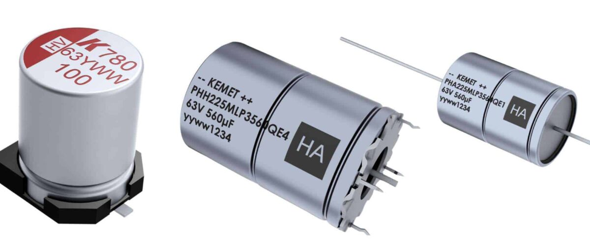
Capacitor Bank Configurations Table
| Configuration | Typical Rating | Application | Switching Device |
|---|---|---|---|
| Fixed bank | 50 – 500 kvar | Constant load, single step | Contactor / LBS |
| Auto bank (LV) | 100 – 1000 kvar | Variable industrial load | Thyristor / contactor |
| MV fixed bank | 1 – 30 Mvar | Substation / plant bus | VCB / SF6 breaker |
| MV switched bank | 2 – 60 Mvar | Voltage regulation | Synchronized breaker |
Switching Requirements for Capacitor Banks
Capacitor switching is one of the most demanding duties for switching devices. When a capacitor bank energizes, the inrush current can reach 10-20 times rated current with high-frequency components, stressing contacts and causing transient overvoltage. The switching device must have the appropriate capacitor switching class per IEC 62271-100, with restrike-free performance for medium voltage applications. Reactors are commonly added in series to limit inrush current and harmonic resonance.
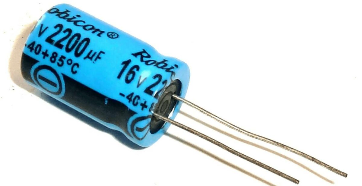
Control and Protection Schemes
Automatic capacitor banks use a power factor controller that measures system PF and switches steps in and out to maintain the target value. Protection typically includes overcurrent protection for each step, overvoltage protection, and unbalance protection using the capacitor neutral current or voltage difference between phases to detect failed elements. For MV banks, dedicated protection relays with overcurrent, overvoltage, and unbalance elements are standard, coordinated with the step switching sequence to prevent hunting.
Harmonics Considerations
Capacitor banks resonate with system inductance at certain frequencies, potentially amplifying harmonics from variable speed drives and other non-linear loads. Before installing a bank, perform a harmonic study to check for parallel resonance near dominant harmonic frequencies. Where resonance is a risk, install detuned reactors set to tune the bank below the dominant harmonic (typically 7% detuning), or use active harmonic filters instead of passive banks.
Commissioning Steps
- Pre-commissioning inspection: Verify connections, torque, insulation, and capacitor element health with a capacitance measurement.
- Insulation tests: Measure phase-to-phase and phase-to-earth insulation resistance.
- Protection checks: Inject test currents into overcurrent and unbalance relays to verify trip functions.
- Energization test: Energize each step in sequence, verify inrush current is within design limits, and confirm PF improvement.
- Control loop test: Simulate load changes and verify the controller switches steps correctly without hunting.
- Documentation: Record settings, test results, and harmonic measurements in the commissioning report.
Frequently Asked Questions
Q1: What is the payback period for a capacitor bank?
For industrial plants with poor power factor, payback is typically 12-24 months through tariff savings, depending on local utility rates and load profile.
Q2: Can capacitor banks cause motor starting problems?
Inappropriately sized banks can overcompensate and cause overvoltage during light load. Properly controlled banks with the correct target PF avoid this issue.
Q3: What causes capacitor failure?
Overvoltage, harmonic resonance, high ambient temperature, and repeated switching stress are the main causes. Proper derating, detuning, and capacitor-rated switching devices extend life.
Q4: How often should capacitor banks be maintained?
Annual inspection includes capacitance measurement, thermal imaging of connections, and verification of protection settings. Fuse checks should be performed after any trip event.
Q5: Do you manufacture complete capacitor bank panels?
Yes, we manufacture LV and MV capacitor bank panels including switching devices, reactors, controllers, and protection, with OEM support for utilities and EPCs.
About Electric-GS Manufacturer
Electric-GS is a professional electrical power equipment manufacturer based in Liushi, Yueqing, Zhejiang, China, with over 15 years of OEM/ODM experience serving global power equipment distributors and EPC contractors. We supply medium and low voltage switchgear, RMUs, circuit breakers, transformers, and solar balance of system products with full type test reports.
Contact us for quotations and custom design support: Email info@electric-gs.com, WhatsApp: +86 135 8897 8050.