
11kV Dual-Infeed Automatic Transfer System Technical Overview (ATS/Auto Transfer)
Keywords: ATS, 11kV, automatic switching, gas-insulated switchgear, dual power supply, smart distribution
1. System Overview
In medium-voltage distribution systems, the “dual-infeed + single output” configuration is commonly adopted to ensure uninterrupted power supply to critical loads. This system typically consists of two incoming lines from separate power sources and one outgoing feeder. An automatic transfer switch (ATS) or controller enables seamless power switching between the primary and backup sources to ensure continuous power even in case of a fault on the primary line.
This configuration is widely applied in urban power systems, industrial complexes, and renewable energy substations, significantly enhancing the continuity and reliability of power supply. It forms a key part of modern smart MV distribution networks.
2. System Composition
2.1 Power Distribution Structure
- Input Line 1 (Primary Source): Typically connected to the main grid and given priority.
- Input Line 2 (Backup Source): Serves as an alternate source when the primary source fails.
- Output Feeder: Supplies power to a transformer or critical load.
- Automatic Transfer Unit (ATS Controller): Core controller responsible for monitoring and switching between sources.
2.2 Switching Logic
- Under normal conditions, the primary source remains active, and the backup source is on standby.
- If the ATS detects loss of voltage, power failure, or frequency anomaly in the primary line, it automatically switches to the backup source based on a pre-set time delay.
- Once the primary power is restored, the system can either automatically revert or require manual switching, depending on configuration.
- Switching delay is adjustable and typically ranges from 300 ms to 60 s, depending on load characteristics.
3. Simplified Single-Line Diagram
    [Input Source A]        [Input Source B]
        [GIS-1]               [GIS-2]
           |                     |
           |                     |
     ----------- ATS Controller -----------
                       |
                    [GIS-3]
                       |
                   [Transformer/Load]
This simplified diagram shows a typical connection for an ATS-based system. Both primary and backup sources are connected via gas-insulated switchgear (GIS) and managed by an automatic transfer controller. The system determines the switching path based on the status of the primary source to ensure uninterrupted load supply.
4. Key Equipment Selection
| Equipment | Recommended Specification |
|---|---|
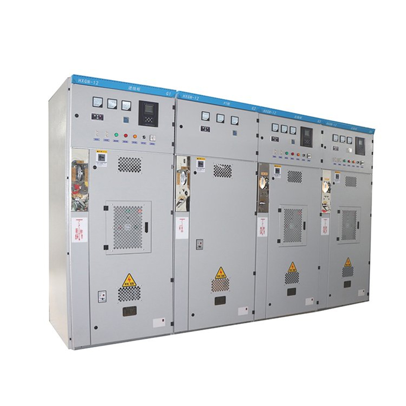
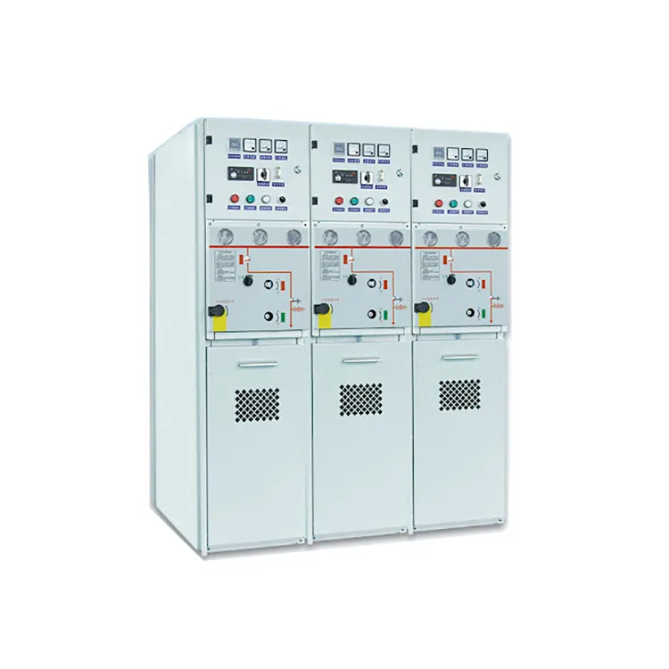
| Gas-Insulated Switchgear (GIS) | 11kV 630A/1250A, 25kA/3s, motorized operation, 3-position (ON/OFF/Earth), indoor/outdoor type |
| Protection Devices | Microprocessor-based devices such as PCS-9710 (NR), NA3000 (NARI), with OC, EF, CB Fail, etc. |
| ATS Controller | PCS-9851, NA-BZT, SCE800 (Eastsoft), supporting multiple logic configurations and delay settings |
| Communication System | Supports IEC 61850, Modbus RTU/TCP; compatible with SCADA/master station integration |
| Cabinet Structure | Compact SF6 gas-insulated RMU, suitable for outdoor installation and smart grid applications |
5. Application Scenarios
This system is ideal for the following applications:
- Urban and Industrial Substations: Nodes requiring high continuity of service.
- Renewable Energy Sites: Such as PV and wind farms, requiring smart switching and remote control.
- Critical Infrastructure: Data centers, hospitals, transport hubs—where outages result in high risks or losses.
- Ring Network Users / Private Substations: Standard for dual-supply, unattended smart substations.
-
ATS/Auto Transfer
6. Remote Monitoring – ‘Three Remotes’ (Telemetry, Signaling, Control)
In modern power distribution systems, especially within medium-voltage automation, the concept of “Three Remotes” — Remote Telemetry, Remote Signaling, and Remote Control — is vital for ensuring real-time visibility and responsiveness of equipment. This functionality enables operators to monitor and manage substations or distribution cabinets remotely, significantly enhancing operational efficiency and system safety.
- Remote Telemetry (遥测): Provides continuous acquisition of analog measurements such as voltage, current, power factor, frequency, and energy consumption. These real-time parameters are essential for power quality analysis and fault diagnostics.
- Remote Signaling (遥信): Reports the status of circuit breakers, disconnectors, protection relays, and other key components. It detects faults like breaker trips, power failures, or earth faults, allowing for immediate alerts to the SCADA system.
- Remote Control (遥控): Allows authorized operators to perform switchgear operations such as opening/closing breakers, resetting faults, or initiating automatic transfer sequences—all from a centralized control room.
Integrated into the ATS system through protocols such as IEC 61850, Modbus, or IEC 104, the “Three Remotes” capabilities ensure that smart distribution networks are not only automated but also intelligent, responsive, and secure.
7. Conclusion
The 11kV dual-infeed + single-output ATS system is a critical solution in ensuring reliable power supply in modern distribution projects. With automatic monitoring, fast switching, and source isolation capabilities, it plays an essential role in enhancing smart grid functionality.
When implementing such systems, it’s essential to carefully consider equipment compatibility, power quality, load demands, and communication topology to ensure the ATS system delivers high reliability, operational flexibility, and intelligent performance across diverse environments.