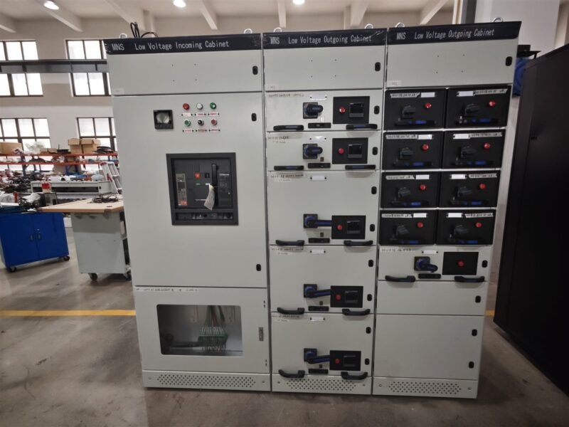
A medium voltage busbar carries the load current between incoming and outgoing feeders inside a switchgear panel. It is a copper or aluminium bar sized to handle normal current and survive short-circuit forces. A well-designed busbar keeps temperature low, joints stable, and the whole panel reliable. This guide explains how to choose and size a medium voltage busbar for 3.6 kV to 40.5 kV switchgear.
Busbar design directly affects cost, footprint, and safety. Oversize it and you pay for wasted copper. Undersize it and the panel overheats or fails under fault. Engineers balance current density, temperature rise, and short-circuit withstand when they pick the bar. The steps below give a practical method for selection.
What Is a Medium Voltage Busbar?
A busbar is a rigid conductive bar that connects several circuits to a common source. In medium voltage switchgear, it runs through the whole panel bay and links the circuit breakers, contactors, and feeders. Busbars can be rectangular bars, round bars, or laminated strips. They are mounted on insulators and covered with a heat-shrink tube or air insulation.
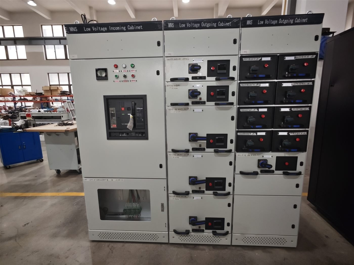
The busbar is the spine of the medium voltage switchgear components. Its rating must match the total load the panel feeds, plus a safety margin for expansion. A busbar failure often takes down every feeder in the bay, so it is worth sizing carefully.
Busbars are also used in transformers, motor control centers, and distribution boards. In every case the design goal is the same: keep the conductor cool at full load and rigid under fault. Good busbar design reduces material cost, saves space in the cubicle, and simplifies field maintenance. The rest of this guide walks through material choice, rating, joints, and testing.
Copper vs Aluminium Busbar
The two common materials are copper and aluminium. The table below compares them for medium voltage use.
| Property | Copper | Aluminium |
|---|---|---|
| Conductivity | Higher, about 101% IACS | Lower, about 61% IACS |
| Weight | Heavy | About one-third lighter |
| Cost | Higher | Lower |
| Corrosion | Better | Needs surface treatment |
| Best use | High current, harsh duty | Long runs, cost-sensitive |
Copper is the first choice in most medium voltage panels because it carries more current in a smaller space. Aluminium suits long bus runs where weight and cost matter more. Whichever you choose, never mix bare copper and aluminium in the same joint without a bimetallic connector.
8 Key Design and Rating Factors
Check these eight factors when you size a medium voltage busbar.
- Continuous current rating. The bar must carry the full load without overheating. Pick a cross-section above the peak demand.
- Temperature rise. Keep the steady-state rise within the class limit, usually 65 K or 70 K for bare copper.
- Short-circuit withstand. Confirm the bar survives the rated fault, for example 25 kA or 50 kA for 3 s, without damage.
- Electrodynamic force. Check the mechanical strength under peak short-circuit forces between parallel bars.
- Cross-section area. Size by current density, typically 1.0 to 1.6 A per square millimetre for copper.
- Insulation distance. Keep phase-to-phase and phase-to-earth clearances per IEC 62271-200 for the rated voltage.
- Surface treatment. Use tinned, silver-plated, or bare bars according to the joint and environment.
- Mechanical mounting. Fix the bar on insulators with enough spacing to avoid vibration and resonance.
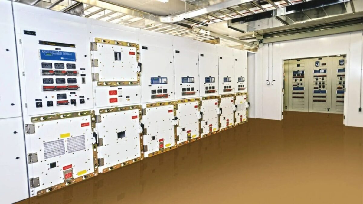
The fault rating is the strictest check. A 50 kA for 3 s duty creates huge forces and heat. Confirm the manufacturer type-test covers this duty before you accept the panel design.
Busbar Joints and Connections
Joints are the weakest point of any busbar. Bolt the connection with the specified torque, apply a conductive joint compound, and keep the surfaces flat and clean. A loose joint heats up and fails over time. For panel assembly, review the medium voltage switchgear selection guide.
Busbar Installation and Testing
Install the busbar on clean insulators and keep uniform clearances. After assembly, run a temperature-rise test at rated current to confirm the joint temperatures stay in range. Do a 10 kV to 40 kV power-frequency withstand test to prove insulation. Add an MV switchgear maintenance routine that retightens joints and inspects the surface each year.
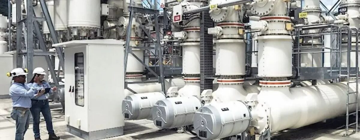
Busbar work inside a ring main unit or a low voltage switchgear panel follows the same principle: clean surface, correct torque, and tight insulation.
A complete factory test includes a partial discharge test at the operating voltage, which reveals voids or sharp edges in the insulation. Thermal imaging during the temperature-rise test shows hot spots at joints. Keep a record of torque values, clearance, and test results for every busbar assembly. This documentation supports the type test certificate and speeds up commissioning on site.
When a panel expands or a substation grows, the busbar must be re-verified. Changing the continuous current or the fault rating changes the cross-section and the joint design. Ask the manufacturer to re-run the calculation and confirm the new duty before you modify an existing panel. Never weld or bolt extra bars without an engineering review.
FAQ About Medium Voltage Busbar
Q1. What is a medium voltage busbar?
It is a copper or aluminium bar that connects incoming and outgoing feeders inside medium voltage switchgear and carries the load current.
Q2. Copper or aluminium busbar, which is better?
Copper carries more current in less space and resists corrosion better. Aluminium is lighter and cheaper for long runs.
Q3. How do I size a busbar?
Choose a cross-section that keeps current density between 1.0 and 1.6 A per square millimetre for copper and confirm the short-circuit rating.
Q4. What is the busbar temperature rise limit?
Most bare copper bars are limited to a 65 K or 70 K steady-state rise above ambient under rated current.
Q5. Why do busbar joints fail?
Loose bolts, oxidation, and poor surface finish raise contact resistance, which heats the joint and causes failure.
Q6. Can I mix copper and aluminium busbars?
Yes, but only with a bimetallic connector. Direct contact between the two metals causes galvanic corrosion.
About Electric-GS
Electric-GS is a Chinese OEM and ODM manufacturer based in Yueqing, Zhejiang. We build medium voltage switchgear, busbars, ring main units and transformers with type-test reports and factory testing. For pricing and drawings, email info@electric-gs.com or reach us on WhatsApp at +86 135 8897 8050. See our main site at electricgs.com and our domestic catalog at electric-cn.com.
Recent Comments