Medium Voltage Current Transformers: Functions and Applications in Power Systems
1. Introduction
In power systems, measurement and protection technologies play a crucial role in ensuring safe and stable operation. Current transformers (CTs), as core components for current signal transmission and transformation, are widely used in grid monitoring, relay protection, automatic control, and energy metering. Especially in distribution systems with voltage levels ranging from 6kV to 35kV, medium voltage current transformers serve as key devices that directly impact the efficiency and safety of the entire power system.
This article systematically explains the basic principles, main functions, structural classifications, typical application scenarios, and selection considerations of medium voltage current transformers, aiming to provide valuable references for power engineering technicians, equipment purchasers, and related practitioners.
2. Definition and Classification of Medium Voltage Current Transformers
2.1 Definition
A medium voltage current transformer is an electromagnetic induction device installed in 6kV to 35kV medium voltage systems, used to convert large primary currents into small secondary currents (usually 5A or 1A) according to a fixed ratio. Its main purpose is to enable low-voltage measuring instruments, relay protection devices, and metering equipment to safely and accurately monitor and process operating currents in the power system.
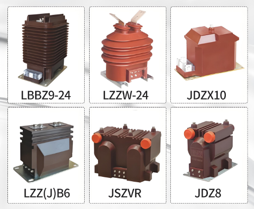
2.2 Classification Methods
Medium voltage current transformers can be classified based on different application functions and structural characteristics as follows:
(1) By Purpose:
-
Measuring CTs: Used for current measurement and energy metering, requiring high accuracy.
-
Protective CTs: Used in relay protection and circuit breaker tripping circuits, focusing on maintaining accurate ratios under fault currents.
-
Combined CTs: Combining measuring and protection functions, equipped with two or more secondary windings.
(2) By Structure:
-
Through-type CTs: Cables or busbars pass through the CT, commonly used in indoor medium voltage switchgear.
-
Epoxy Resin Cast CTs: Using epoxy resin for overall casting, suitable for indoor environments.
-
Porcelain Insulated CTs: With porcelain insulating shells, commonly used in outdoor substations.
-
Dry-type CTs: Oil-free and gas-free, environmentally friendly, suitable for urban distribution and intelligent switchgear.
-

Medium Voltage Current Transformers
3. Main Functions of Medium Voltage Current Transformers
3.1 Current Signal Transformation
Due to the large currents in primary circuits, they cannot be directly sent to instruments or protection devices. Medium voltage current transformers use magnetic induction principles to convert primary currents into small secondary currents (e.g., 5A or 1A) suitable for secondary systems, achieving electrical isolation and signal conversion.
3.2 Relay Protection
Relay protection systems use medium voltage current transformers to collect fault current signals, determine short circuits, overloads, grounding, and other abnormal conditions, and promptly issue tripping commands to protect power equipment and personnel safety.
3.3 Energy Metering
Metering CTs typically have accuracy classes of 0.2S, 0.5S, or 1.0, ensuring high-precision energy statistics over a wide current range, serving as an important basis for power trading settlement and energy efficiency analysis.
3.4 Operational Monitoring and Automation Control
In conjunction with medium voltage intelligent switchgear, monitoring terminals, or substation automation systems, medium voltage current transformers can achieve remote current collection, fault location, power dispatching, and other functions, forming an integral part of modern smart grids.
4. Working Principle and Structure of Medium Voltage Current Transformers
4.1 Working Principle
Medium voltage current transformers operate based on electromagnetic induction principles. When a large current flows through the primary side, the winding generates a magnetic field, creating magnetic flux in the core, inducing a small current in the secondary winding proportional to the primary current. The transformation ratio is determined by the number of turns in the windings, ideally satisfying:
I₁ × N₁ = I₂ × N₂
Where I₁ is the primary current, N₁ is the number of primary winding turns, I₂ is the secondary current, and N₂ is the number of secondary winding turns.
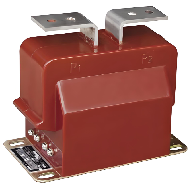
4.2 Structural Components
Medium voltage current transformers mainly consist of the following parts:
-
Primary Conductor: Directly connected to the medium voltage circuit, carrying the operating current.
-
Core: Made of high-permeability silicon steel sheets, used for magnetic flux transmission.
-
Secondary Winding: Coils wound on the core, connected to secondary instruments.
-
Insulation Structure: Epoxy resin, dry-type insulation, or ceramic shells to ensure voltage withstand capability.
-
Terminal Blocks and Nameplates: Used for connection, identification, and debugging.
5. Application Scenarios of Medium Voltage Current Transformers
Medium voltage current transformers are widely used in various 6kV to 35kV medium voltage systems, mainly including:
5.1 Industrial and Mining Enterprise Distribution Systems
Industries such as steel, chemical, coal mining, and ports extensively use 10kV/6kV distribution systems. Medium voltage current transformers are installed inside switchgear, working with protective relays to quickly isolate faults.
5.2 Municipal Power Grid Substations
Urban power grids commonly use 10kV ring main units, box-type substations, and GIS switch stations equipped with medium voltage current transformers for SCADA data collection, energy metering, and remote protection.
5.3 Power Plants/New Energy Access Systems
Wind power, photovoltaic, gas-fired power generation, and other units connect to the main grid through 35kV medium voltage step-up stations, requiring high-precision medium voltage current transformers for generation data monitoring and fault isolation.
5.4 Rail Transit and Data Centers
Medium voltage power supply systems adopt intelligent medium voltage current transformers, combined with protection devices to achieve rapid fault detection and distribution automation functions, ensuring high-reliability operation.
6. Technical Parameters and Selection Considerations for Medium Voltage Current Transformers
In engineering design or equipment procurement, correct selection of medium voltage current transformers is crucial, requiring attention to the following key parameters:
6.1 Voltage Level and Insulation Level
Should meet the system’s rated voltage and withstand voltage requirements, such as 12kV, 24kV, 36kV, with corresponding power frequency withstand voltage, lightning impulse withstand voltage, etc., complying with IEC standards or GB/T 20840.
6.2 Rated Primary Current and Transformation Ratio
Select the primary current value (e.g., 300A, 600A, 800A, 1200A) based on the main circuit’s maximum current, and configure the transformation ratio (e.g., 600/5, 800/1) according to relay or metering device requirements.
6.3 Accuracy Class
-
For Measurement: Recommended to use 0.2S or 0.5S accuracy.
-
For Protection: Use high accuracy limit factor CTs like 5P10, 10P20.
-
For Combined Measurement and Protection: Use dual-winding CTs.
6.4 Thermal and Dynamic Stability Current
Ensure the CT body is not damaged or burned under fault conditions, such as rated thermal stability current Ith of 20kA/1s, dynamic stability current Idyn of 50kA, etc.
6.5 Installation Method and Size Interface
Choose through-type, pillar-type, or cabinet-type structures according to switchgear structures (e.g., KYN28, HXGN, XGN15), paying attention to the matching of primary conductor openings, mounting rails, or base plate hole sizes.
7. Development Trends of Medium Voltage Current Transformers
With the development of smart grids, green energy, and distribution automation, medium voltage current transformers are showing the following trends:
7.1 Intelligence
Integrating sensors, communication modules, and digital interfaces to achieve primary signal to digital output (e.g., Modbus, IEC 61850), supporting remote measurement, control, and adjustment functions.
7.2 Oil-free and Environmentally Friendly
New medium voltage CTs generally adopt dry-type, epoxy resin fully enclosed structures, avoiding oil-immersed aging issues, more suitable for urban substations and underground switch stations.
7.3 High Safety and Low Power Consumption Design
Enhancing insulation performance and isolation design, using low-power magnetic cores and optimized coil structures to improve long-term operational stability and reliability.