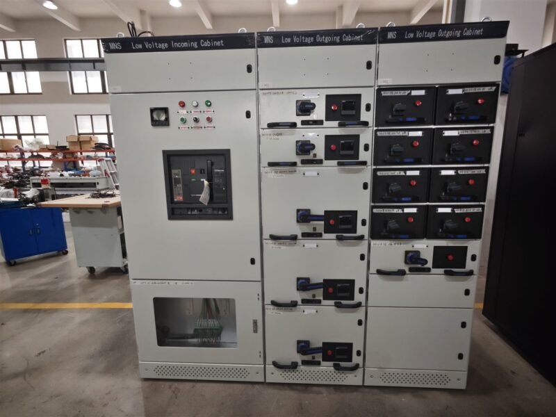
Two generators running side by side are not a parallel system. Until their voltages, frequencies and phase angles agree, closing a breaker between them is a fault, not a transfer. Paralleling switchgear exists to make that moment safe, then to keep it safe for the next ten years.
What Paralleling Switchgear Actually Does
The gear is a control and protection package built around the breakers that tie generators together and to the load. Four functions sit inside it:
- Synchronizing: it watches voltage, frequency and phase angle, and closes the breaker only inside a defined window.
- Load sharing: it splits real and reactive load across running sets by trimming fuel or excitation.
- Protection: reverse power, overcurrent, underfrequency and breaker failure are wired per set, not per bus.
- Sequence control: start, connect, shed and stop are carried out in order, with interlocks that will not be bypassed.
Get those four right and a plant rides through a utility outage. Get one wrong and the first transfer test ends with a damaged alternator.
Step 1: Define the Duty and the Redundancy
Everything downstream depends on one answer: is the plant standby, prime power or continuous? A standby plant may run a few hundred hours a year and can accept a short break. A prime power plant on an island cannot.
- Load profile: list peak and average kVA per set after derating for altitude, ambient and fuel quality.
- Redundancy: decide N, N+1 or 2N, and state what happens when one set trips mid-outage.
- Transfer behaviour: open transition, closed transition, or soft load transfer with a short parallel time.
- Growth: leave busbar and panel space for one more set, or you will rebuild the lineup in three years.
Write these numbers into the specification. A paralleling scheme that is “sized later” always ends up undersized.
Step 2: Choose Between LV and MV Paralleling Gear
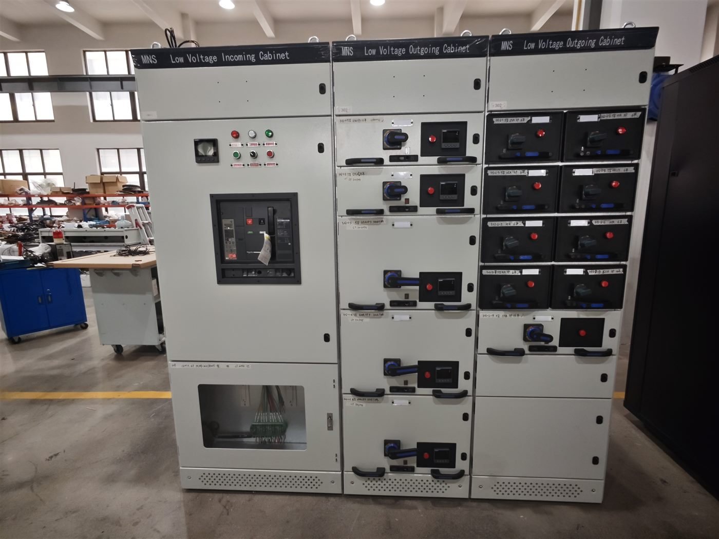
Below roughly 1 MW the LV route is cheaper and easier to maintain. Above that, cable and breaker sizes push the design toward MV, where a single 11 kV feeder can carry what three LV feeders cannot.
| Item | LV paralleling gear | MV paralleling gear |
|---|---|---|
| Typical system voltage | 380 to 690 V | 11, 22 or 33 kV |
| Breaker type | MCCB or ACB, fixed or drawout | VCB or SF6 breaker, drawout |
| Practical set size | Up to about 1 MW per set | 1 to 20 MW per set |
| Sync device | Auto synchronizer with check-sync relay | Same, plus voltage and phase monitoring per feeder |
| Load sharing | kW and kvar via engine and excitation control | Same, with transformer and feeder losses in the loop |
| Footprint | Wide lineup, short cable runs | Compact lineup, longer, more expensive cable |
| Typical use | Buildings, plants, small IPP sites | Utility-scale standby, industrial sites, substations |
Panel construction follows the same rules as any distribution board, so the component and enclosure choices in our LV switchgear guide apply directly to the LV case.
Step 3: Specify Synchronization and Load Sharing
Synchronizing is a measurement problem before it is a control problem. Specify the window, not just the device:
- Voltage difference under 5 percent, frequency difference under 0.2 Hz, phase angle within 10 degrees.
- A check-sync relay wired in series with the close coil, independent of the controller.
- Dead bus closing enabled only when the bus is proven dead, not assumed dead.
- Reverse power protection set low enough to catch a set that loses its prime mover.
For load sharing, choose isochronous control when frequency must stay fixed and droop control when sets of different sizes share a bus. Mixed control on one bus causes hunting that no amount of tuning fixes.
Step 4: Protect, Interlock and Fail Safe
Paralleling gear sits between two sources, so it needs protection that points in both directions. Protection relays selected from our protection relay guide should cover:
- Reverse and low forward power per generator.
- Overcurrent and earth fault on each generator feeder.
- Under and overvoltage, under and overfrequency, with separate settings for island and parallel modes.
- Breaker failure, plus a trip path that does not depend on the controller.
- Mechanical and key interlocks between utility and generator feeds, and between two incomers.
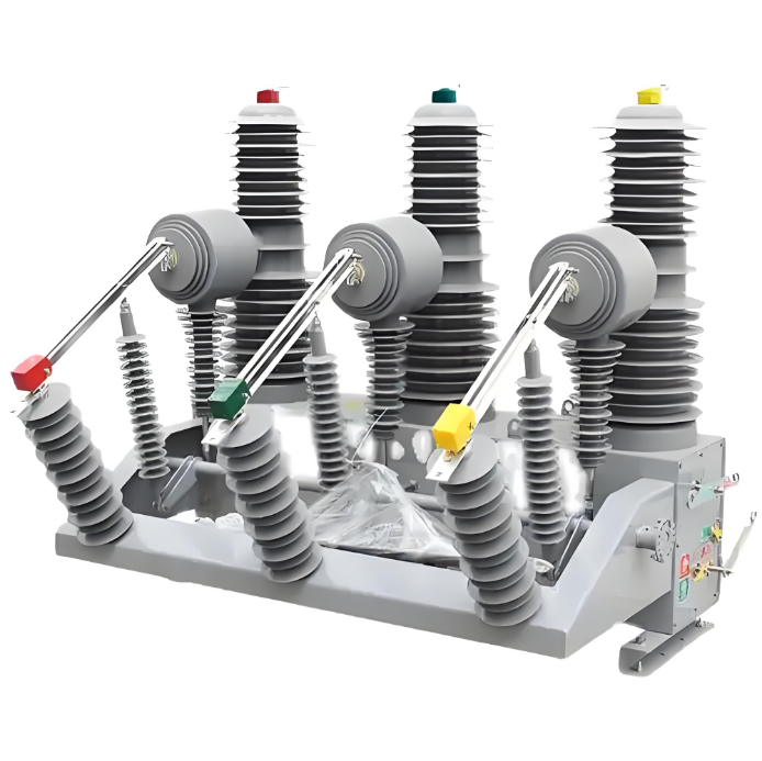
The vacuum breaker guide explains the switching duty these breakers see during repeated transfers, which is harsher than a normal feeder duty cycle.
Step 5: Test, Commission and Document
A paralleling system is proven by tests, not by a wiring check:
- Factory test each panel: insulation, contact resistance, interlock function, relay injection.
- Witness the first parallel at low load, with the sync window recorded from the controller.
- Run a load share test at 25, 50 and 75 percent, and log kW and kvar per set.
- Prove one set trips: the remaining sets must pick up load without exceeding their rating.
- Prove a dead bus start and a utility return, including the cool-down timer.
Hand over a document set that matches the plant: single line, control schematics, relay settings, sync window, test sheets and the as-built logic. Without the settings file, the next engineer starts from zero. Our 10-step maintenance plan shows where these checks sit in the yearly cycle, and the transformer protection guide covers the step-up side when the plant exports power.
Frequently Asked Questions
Can generators be paralleled without a synchronizer?
Only manually, with a synchroscope and a trained operator, and only on small sets. Automatic paralleling gear exists because manual closing outside the window damages alternators.
What happens if the phase angle is wrong at closing?
A large circulating current flows in an instant, stressing the winding, the shaft and the breaker. Repeated closes outside the window shorten alternator life even when nothing visibly fails.
Do I need reverse power protection?
Yes, on every set. If the prime mover stops while the breaker is closed, the generator becomes a motor and draws power from the bus.
Is N+1 always the right redundancy?
Only when the remaining sets can carry the critical load after one trips. Check the post-trip load, not the total installed capacity.
Can LV and MV paralleling gear share one control scheme?
The control logic is similar, the hardware is not. Cable capacitance, breaker types and protection settings differ, so specify each lineup against its own voltage.
How long should the first parallel test run?
Long enough to see steady load share at three load points, plus one forced trip. A short test proves the wiring, not the system.
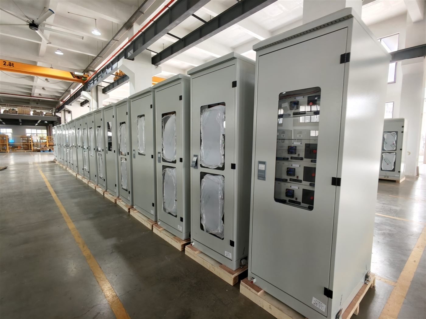
Electric-GS manufactures ring main units, gas insulated and air insulated switchgear, vacuum circuit breakers and LV distribution boards in Yueqing, China. We build for OEM and ODM projects and test every panel before dispatch. For drawings, specifications or a quotation, write to info@electric-gs.com or message WhatsApp +86 135 8897 8050. More references are on electricgs.com and electric-cn.com.