Comprehensive Overview of Voltage Transformers
1. Introduction
In modern power systems, the Voltage Transformer (VT), also known as a Potential Transformer (PT), plays a vital role in measurement, protection, and control. Since the voltage levels in power networks are usually very high and cannot be measured directly for safety and practical reasons, voltage transformers are used to proportionally reduce the high voltage to a measurable and safe value. This article provides a comprehensive overview of the structure, principles, classification, application, selection, and future development of voltage transformers.
2. Basic Concept of Voltage Transformer
A voltage transformer is an electromagnetic induction device used to convert high voltage into a standardized, measurable low voltage. Its basic structure is similar to a power transformer and consists of a primary winding, a secondary winding, and a magnetic core. The main functions include:
-
Measuring system voltage through instruments;
-
Providing input to protection relays;
-
Metering in conjunction with current transformers (CTs);
-
Detecting system faults like overvoltage or grounding.
-
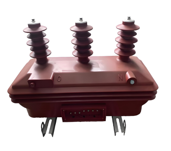
Voltage Transformers
3. Classification of Voltage Transformers
1. By Insulation Medium
-
Dry-type VT: Uses epoxy resin or air insulation; suitable for ≤10kV systems; features compact size, easy installation, and low maintenance.
-
Oil-immersed VT: Uses insulating oil; suitable for 35kV and above; offers high insulation and thermal stability.
-
Gas-insulated VT (GIS type): Used in ultra-high-voltage systems (220kV+); often integrated into GIS switchgear, providing high insulation strength and compact design.
2. By Functional Structure
-
Single-phase VT: Measures voltage in single-phase systems.
-
Three-phase VT: Measures voltage in three-phase systems.
-
Open delta (V-V) VT: Detects zero-sequence voltage for earth fault detection.
-
Capacitive Voltage Transformer (CVT): Extracts voltage signal and supports carrier communication in high-voltage transmission lines.
-
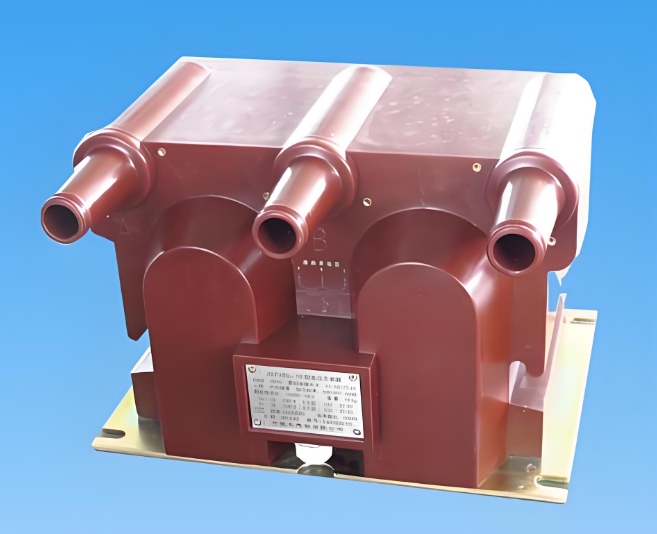
Voltage Transformer
4. Working Principle
The working principle of a voltage transformer is based on electromagnetic induction. The primary side is connected to the high-voltage circuit, and the magnetic flux induces a proportional low voltage on the secondary side for measurement or protection.
The basic formula is:
V2=V1×N2N1V_2 = V_1 \times \frac{N_2}{N_1}
Where:
-
V1V_1: Primary voltage;
-
V2V_2: Secondary voltage;
-
N1,N2N_1, N_2: Turns of primary and secondary windings.
Typical design parameters:
-
Secondary output voltage: 100V or 110V;
-
Stable voltage ratio;
-
Reliable insulation between primary and secondary circuits.
-
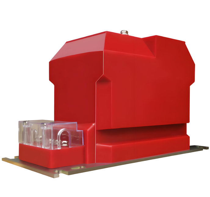
Voltage Transformer
5. Main Applications
1. Voltage Measurement
Provides a safe and accurate voltage signal for voltmeters, power meters, and monitoring systems.
2. Relay Protection
Supplies voltage inputs to protection devices for:
-
Overvoltage/undervoltage protection;
-
Zero-sequence voltage protection (for earth fault);
-
Voltage blocking, tripping, and automatic switching logic.
3. Energy Metering
Works with CTs to provide accurate voltage signals for high-voltage metering and energy billing.
4. Control and Automation
Used in voltage regulation, synchronization, remote terminal units (RTUs), and SCADA systems.
6. Selection Principles
1. Rated Voltage
The VT’s primary voltage should match the system’s nominal voltage (e.g., 10kV system → 10kV VT).
2. Accuracy Class
Different applications require different accuracy levels:
-
Measurement: 0.5 or 0.2 class;
-
Billing metering: 0.2S or 0.5S class;
-
Protection: 3P or 6P class.
3. Load Capacity
Total secondary load (instruments, wiring, etc.) should not exceed VT’s rated burden.
4. Insulation and Environment
Choose dry-type or oil-immersed based on location (indoor/outdoor), temperature, and humidity.
5. Compliance and Safety
Ensure compliance with IEC or local standards (e.g., IEC 61869, GB1207); VTs should withstand short circuits and overvoltage.
7. Installation and Use
1. Installation Guidelines
-
Ensure proper grounding, especially on the secondary side;
-
Never leave the secondary circuit open while energized to avoid high voltage hazards;
-
Follow nameplate wiring instructions carefully.
2. Commissioning and Testing
-
Verify ratio, polarity, and insulation resistance;
-
Conduct dielectric tests and burden tests;
-
Ensure the protection circuit is functional and responsive.
8. Common Faults and Troubleshooting
| Fault Type | Cause | Solution |
|---|---|---|
| Secondary open circuit | Broken wire or poor contact | Disconnect power and reconnect |
| Accuracy degradation | Core saturation or aging | Recalibrate or replace |
| Overheating/failure | Insulation aging, ambient heat | Replace VT or improve ventilation |
| Noise/vibration | Loose core or harmonic interference | Retighten core or replace VT |
9. Future Development Trends
With the advancement of smart grids and digital substations, VTs are evolving toward:
1. Intelligent VTs
-
Digital signal output (IEC 61850-9-2);
-
Online monitoring, fault recording;
-
Integration with automation and control systems.
2. Optical VTs (OVTs)
-
Use optical technology instead of electromagnetic induction;
-
High precision, lightweight, and safe;
-
Ideal for UHV and intelligent substations.
3. Miniaturization and Modularization
-
Compact designs for use in RMUs and compact switchgear;
-
Easy integration into secondary devices.