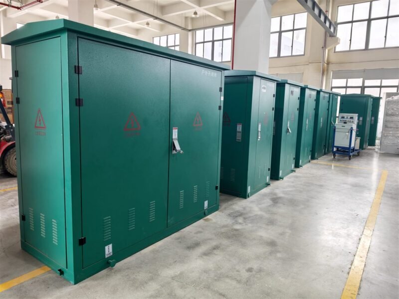
A tripped feeder is a question: which cable failed, and where. Cable fault location answers it in two stages. First you measure the distance from the test end. Then you walk to that distance and listen. Done in that order, a fault that could cost a week of open trenching is found in a few hours.
Why a Method Beats a Shovel
Most MV cable failures start small. A damaged sheath lets moisture in, water trees grow in the insulation, and the cable finally breaks down under load. The breakdown point is often under a road, a yard or a wall, while the visible damage sits metres away at a joint.
A location survey turns guesswork into a distance. You still need to dig, but you dig once, at the right place, with the right joint kit on the truck.
- Time saved: a planned repair instead of a search.
- Cost saved: one excavation, not three trial pits.
- Risk saved: no repeated energising of a damaged cable to “see if it holds”.
Step 1: Classify the Fault Before You Test
The fault type decides the method. Write it down before connecting anything:
- Open circuit: a phase is disconnected, often after a joint failure or a mechanical pull.
- Short circuit to earth or between phases: low resistance, easy to see on a reflection trace.
- High resistance fault: the cable fails under voltage but reads clear on a low-voltage meter. Common on water-damaged insulation.
- Flashing or intermittent fault: fails only at a certain voltage, load or weather. The hardest case.
- Sheath or jacket fault: the conductor is healthy; the outer layers are damaged and corroding.
Record test results, weather, load at trip and any recent excavation near the route. That history narrows the search before a single pulse is sent.
Step 2: Prove Dead, Isolate and Earth
Location testing puts voltage on a cable that the owner believes is faulty. Treat it as live work:
- Open the feeder at both ends, and prove the cable dead at the test point.
- Earth the remote end, or guard it, so no one can contact it during testing.
- Disconnect surge arresters and sensitive equipment from the test end.
- Barricade the test area and keep non-essential people out of the thump zone.
- Follow the site permit and your lockout procedure, every time.
If you need the surrounding switchgear checked before testing, our 10-step maintenance plan covers the isolation and inspection sequence in the same order.
Step 3: Pre-Locate the Distance
Pre-location gives a number, usually in metres from the test end. Two instruments do most of the work:
Time domain reflectometry sends a low-energy pulse and times the echo. It needs the cable’s propagation velocity, which is printed on the drum or listed for the insulation type. A clean open or short shows as a clear reflection; a wet, high-resistance fault may show nothing at all.
Arc reflection adds a surge to burn the fault into a low-resistance path for a moment, so the reflectometer can see it. That is the standard method for MV cable that fails only under voltage.
Then compare the measured distance with the route drawing. If the number lands near a known joint, a bend or a road crossing, the probability of a correct dig goes up sharply.
Step 4: Pinpoint the Exact Spot
A pre-located distance is a zone, not a point. Pinpointing needs a signal you can hear or measure at the surface:
- Surge thumping: a capacitor discharges into the fault and the arc makes an audible thump. Walk the zone and listen.
- Acoustic and ground microphone: amplifies that thump through soil, useful on busy streets.
- Voltage gradient: two probes measure step voltage around a sheath fault, no sound needed.
Start at the pre-located distance, work outward, and mark the strongest signal. On direct-buried cable the loudest point is usually within half a metre of the fault.
Once the conductor is exposed, confirm the damage before cutting. A cable that has flashed over often shows charring along the insulation away from the entry point, and the partial discharge test tells you whether the rest of the section is still sound.
Step 5: Repair, Retest and Record
The repair is only finished when the cable passes a test. Sequence that works:
- Cut back to undamaged insulation, not to the first clean-looking metre.
- Use a joint kit rated for the insulation type, voltage and installation condition.
- Re-make the sheath and the earth continuity path; moisture returns through a bad sheath.
- Test insulation resistance and run a withstand test at the specified voltage and time.
- Record the fault distance, method, repair type and final test values.
A fault that repeats in the same zone within a year usually means the repair was too short, or the cause was never removed. Check for a damaged duct, a missing bedding layer or water entry from an outdoor enclosure before blaming the joint.
Comparing Six Location Methods
| Method | Finds | Typical accuracy | Use it when |
|---|---|---|---|
| Time domain reflectometry | Opens and low-resistance shorts | About 1 m in 100 m | First pass on every fault |
| Arc reflection | High-resistance MV faults | 1 to 2 m | Reflectometer trace is flat |
| Decay method | Very high resistance, flashing faults | Percentage of length | Thumping is not allowed |
| Surge thump | Pinpoint by sound | 0.5 to 1 m | After pre-location, open route |
| Acoustic and ground mic | Pinpoint in noisy areas | Under 1 m | City streets, hard surfaces |
| Voltage gradient | Sheath and jacket faults | About 1 m | Direct-buried cable, no sound path |
Cable construction matters too. Conductor size and insulation wall set the pulse behaviour and the test voltage, which is why the selection rules in our MV cable sizing guide and the test levels in the switchgear testing guide are worth reading before the van leaves.
Frequently Asked Questions
Can a cable fault be located while the cable is energised?
No. Location testing injects a surge or a pulse. De-energise, prove dead, earth the remote end and work under a permit.
What if the reflectometer shows no reflection?
That usually means a high-resistance or flashing fault. Switch to arc reflection or the decay method instead of repeating the same pulse.
How accurate is pre-location?
Typically around 1 percent of cable length. Use it to define an excavation zone, then pinpoint by sound before digging.
Do I need the exact cable length?
Yes. Length error becomes distance error, so take the length from records or measure it, and confirm the propagation velocity for that cable type.
Can thumping damage a healthy cable?
It can if energy is set too high. Use the lowest level that gives a clear signal, and never thump a cable you have not pre-located.
What records should be kept?
Fault type, method, measured distance, repair details and post-repair test values. Those records shorten the next fault on the same feeder.
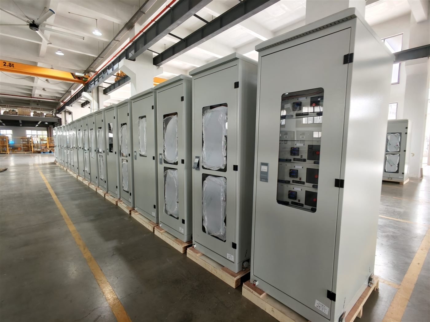
Electric-GS manufactures ring main units, gas insulated and air insulated switchgear, vacuum circuit breakers and LV distribution boards in Yueqing, China. We build for OEM and ODM projects and test every panel before dispatch. For drawings, specifications or a quotation, write to info@electric-gs.com or message WhatsApp +86 135 8897 8050. More references are on electricgs.com and electric-cn.com.