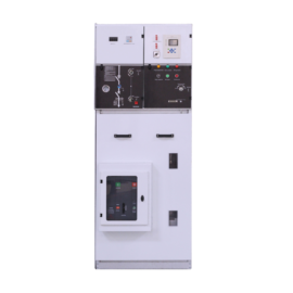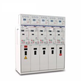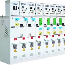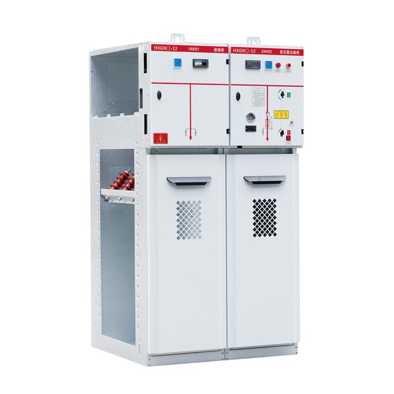

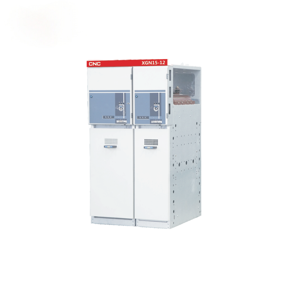

Rating: Rated voltage 3~12KV, rated current reach to 630A for load break switch and 125A for combined switchgear.
Application:
mainly applicable in urban power grid features and renovation project, industrial and mining enterprises. high-rise buildings and communal facilities .For power distribution, controlling and protection on electric equipment as the loop power supply unit or
terminal equipment. It also can be installed in pre-loaded substation.
Feature:
Equipped with vacuum load switch and spring operating mechanism which can be operated by hand or electric. Grounding switch and insulating switch are equipped with hand operating mechanism .With small volume and high security.
Standard: IEC60420

1. Ambient air temperature: -15℃ ~+40℃ .
Daily average temperature:≤35℃ .
2. Altitude: ≤1000m.
3. Relative humidity : Daily average≤95% ,daily averange of vapour pressure≤2.2kpa
Monthly average≤90%,monthly averange of vapour pressure≤1.8kpa.
4. Earthquake intensity: ≤magnitude 8.
5. Applicable in the places without corrosive and flammable gas.
Note: Customized products are available.
| No. | Item | Unit | Data | |
| 1 | Rated voltage | kV | 12 | |
| 2 | Rated current | Load break switchgear | A | 630 |
| Combined switchgear | A | 125 | ||
| 3 | Rated short-circuit breaking current | kA | 31.5 | |
| 4 | Rated active on-load breaking current | A | 630 | |
| 5 | Rated short-time withstands current | kA | 20 | |
| 6 | Rated withstands current(Peak) | kA | 50 | |
| 7 | Rated power frequency voltage withstands | kV | 42/48 | |
| inter-phase,to earth and to the open contact | ||||
| 8 | Thundering withstands voltage inter-phase, | kV | 75/85 | |
| to earth and to the open contact | ||||
| 9 | Mechanical life | times | 10000 | |
| 10 | Rated take-over curent | A | 3150 | |
| 11 | Operating mode | / | Manual or automatic | |
| 12 | Protection level | / | IP2X | |
The loop power supply is composed of three basic unit to separate any one of the failure line and ensure the continuous power supply through the other unit. The branch line for the user could separated and protect the transformer which could facilitate the maintenance. The loop power supply could be expanded as per the user’s requirements to form various protection plans.
Picture 1

1. 8MF material adopted for the switchgear,modular holes available with E=200.
2. Switch disconnector ,vacuum load breaker switch, earthing switch and the switchgear door reliably interlocked,which could avoid miss operation.
3. Both manual and automatic operation are available.
4. There isleas sealed pin at the door of measurement chamber and meter chamber.
5. Prompt tripping could be realized to protect the equipments.
6. The design facilitate the operation at the front panel and the switchgear could be installed alongside the wall.
7. The switchgear is featured for its complete interlocking function: the load break switch could be operated to the making status when the switchgear door is closed and locked and the earthing switch to the making position.
When the earthing switch is at making status, input the insulation clapboard to its position, the switchgear door then, could be operated.
8. The Vacuum arc-extinguishing chamber and fuse are reliably connected. So as the fuse & switchgear door and insulation clapboard & the switchgear door.
Picture 2

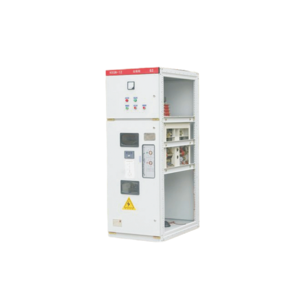
1. Earthing switch 2. Operating mechanism 3. Bushing 4. Insulator 5. Cut out fuse
6. Spring operating mechanism 7. Load break switch 8. CT

Main single line diagram Sheet 2


Continued Sheet 2


Continued sheet 2